Uncategorized
Easily Solve Common Electronic Control System Issues

February 12, 2025
Share:
 autoolstore.com
Electronic control system basics
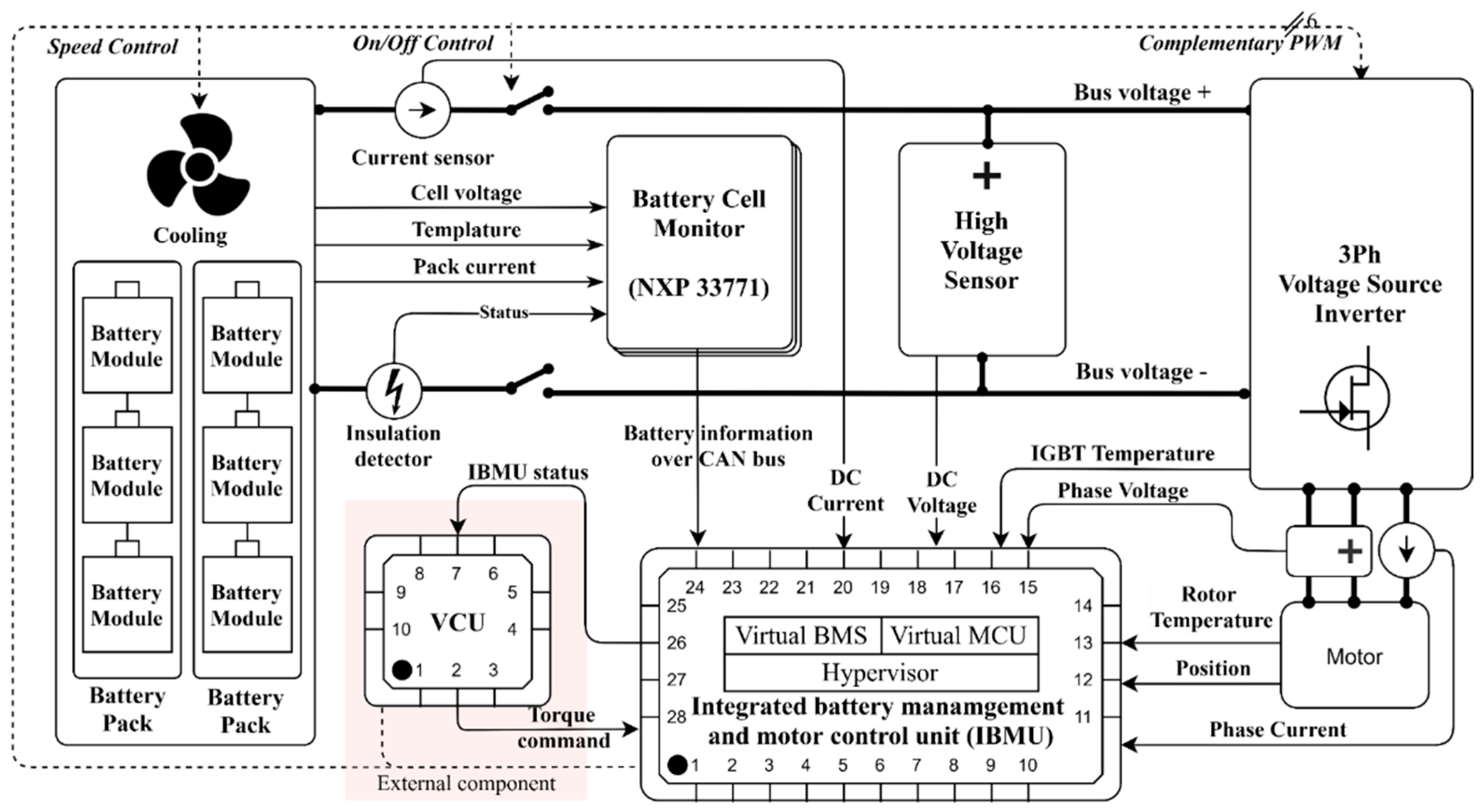
The electronic control system is responsible for coordinating important EV functions, including power output, charging management, power distribution, braking coordination, and system protection. Its key modules include the Battery Management System (BMS), Motor Control Unit (MCU), and Vehicle Control Unit (VCU).
A simple way to understand the relationship is: VCU equals the brain or decision-making center, MCU equals the spinal cord or command transmission layer, and BMS equals the energy management organ that monitors the battery pack.
Battery Management System
BMS faults can cause inaccurate power display, abnormal charging, overheating warnings, or battery health detection issues.
Motor Control Unit
MCU faults may lead to unresponsive acceleration, power lag, abnormal motor heating, or sudden power loss.
Vehicle Control Unit
VCU problems can cause persistent warning lights, start failure, power interruption, or the need for software reset or replacement.
Voltage and overload faults
Too-low voltage, too-high voltage, overload protection, overcharging, or over-discharging can all trigger electronic control system warnings.
Symptom to inspection point
When an electronic control system warning appears, the first step is not to disassemble components. Start from the visible failure phenomenon, then decide what the owner can safely observe and what a repair store should test.
| Failure phenomenon | Primary investigation point | Owner self-inspection method | Repair store test item |
| Power suddenly interrupted | 12V small battery voltage | Use a USB voltage detector to measure the cigarette lighter output. | VCU power supply relay impedance test |
| Charging gun cannot be unplugged | Electronic locking mechanism | Confirm the emergency pull-rope position from the vehicle diagram or manual. | CP signal waveform analysis |
| Energy recovery system failure | Wheel speed sensors | Observe tire pressure monitoring data and related vehicle status information. | Braking energy recovery MAP calibration |
Electronic control system troubleshooting process
The table below keeps the original diagnostic logic but organizes it into a clearer workflow. A warning may involve more than one module, so fault-code reading, battery health detection, voltage monitoring, and wiring checks should be considered together.
| Fault type | Common trouble | Diagnostic steps | Solutions |
| Battery Management System (BMS) failure | Inaccurate power display or charging abnormality | Read OBD fault codes and check battery health status. | Repair battery connections or replace damaged batteries. |
| Battery Management System (BMS) failure | High-temperature warning light or battery overheating | Check whether battery connections are loose. | Replace the BMS if necessary. |
| Motor Control Unit (MCU) failure | Unresponsive acceleration or power lag | Read MCU fault codes and inspect motor connections. | Repair power or signal-line faults. |
| Motor Control Unit (MCU) failure | Abnormal motor heat or loss of power | Check the motor, its connections, and motor load. | Check the cooling system or replace the motor if necessary. |
| Vehicle Control Unit (VCU) malfunction | The vehicle loses power or will not start | Scan for VCU fault codes and check VCU input voltage. | Perform a software upgrade or reset, then replace the VCU unit if necessary. |
| Vehicle Control Unit (VCU) malfunction | Fault light stays on or flashes | Try an electronic control system restart when appropriate. | Check battery pack voltage stability before replacing hardware. |
| Abnormal voltage or overload fault | Battery voltage is too low or too high | Monitor battery voltage fluctuations. | Adjust the output current of the charging equipment. |
| Abnormal voltage or overload fault | Electrical control system overload protection | Check the status of the charging system. | Check battery charging and discharging conditions to avoid overcharging or over-discharging. |
Owner’s edition
This layer applies when a malfunction warning light, power abnormality, or system error appears while driving. The priority is to keep the vehicle safe, record the original fault condition, and avoid actions that erase useful data.
The forced reset operation is only suitable for soft faults, such as a frozen vehicle system, garbled dashboard display, or temporary function-button failure. It should not be used to ignore a serious high-voltage warning.
Low-voltage power reset
Open the trunk, locate the negative terminal of the 12V small battery marked “-”, disconnect it with a 10mm wrench, wait 5 minutes, then reconnect it and start the vehicle to see whether the fault disappears.
Vehicle system button reset
Long press the vehicle power button and volume knob for about 15 seconds. For Tesla Model 3, the original note describes a double-scroll-wheel long press.
Vehicle-specific reset examples
For NIO ES6, press and hold “Menu + Volume Down” on the steering wheel until the logo appears, about 20 seconds. For Li Auto ONE, a physical “Forced Reboot” button may be triggered with a card pin.
Reset risk limit
Do not perform forced reboot more than 3 times per month. Frequent power cuts may damage memory. If a “Maximum Speed Limit” message appears after reboot, the vehicle should be serviced immediately.
Technician’s edition
Technician-level work focuses on locating hidden faults that cannot be confirmed from dashboard warnings alone. These procedures involve electronic signals, historical BMS data, insulation safety, and controlled load testing.
Oscilloscope testing can detect motor rotation signals, CAN bus waveforms, and PWM drive pulses. In the original motor rotation sensor case, normal sine and cosine waveforms should be symmetrical in amplitude, with a typical value of 2.5V ± 0.2V, and the phase difference should remain 90 degrees. A deviation greater than 5 degrees is abnormal. Waveform distortion may indicate a broken sensor ring that requires motor disassembly, while signal interruption suggests checking the sensor power supply line, where the normal voltage is 5V ± 0.1V.
Historical BMS data can help locate hidden charging or discharging faults. Export BMS charging data and focus on timestamp, unit voltage, and temperature cluster. Then generate a voltage-time curve in Excel. A normal curve rises smoothly, and the voltage difference between neighboring units should be less than 30mV. A voltage drop greater than 100mV in a specific unit may indicate a loose connecting tab.
Charging pile logs can also be cross-compared by obtaining real-time current and voltage through Modbus protocol. This comparison helps determine whether the fault comes from the vehicle side, charging equipment, or communication layer.
The purpose of a stress test is to reproduce occasional faults and verify the repair effect. For an IGBT module temperature rise test, connect a thermal imager such as FLIR E8 and align it with the motor controller heat sink. Then activate “Full Load Mode” with the diagnostic instrument and simulate continuous acceleration from 0-100km/h for 10 times.
Cross-version common precautions
Good collaboration between the vehicle owner and technician can shorten diagnosis time. The owner should provide a complete record of the conditions that triggered the fault. The owner should not clear fault codes by themselves, because critical diagnostic data may be lost.
Do not touch high-voltage components
Direct contact with high-voltage components without insulated gloves is a red-line operation, even if the system appears de-energized.
Do not use non-isolated power supply
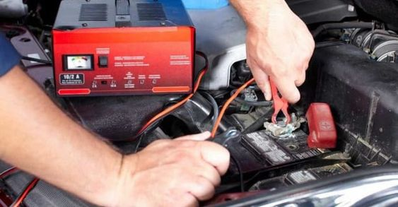
Using a non-isolated power supply to power the vehicle controller may cause a short circuit and damage the controller.
Preventive maintenance
Electronic control system failures are not impossible to solve. With basic fault-code reading, careful fault recording, system checks, and simple maintenance, vehicle owners and technicians can identify common issues more quickly and keep the vehicle running smoothly. The key is to separate safe owner-level checks from technician-level high-voltage work, preserve useful diagnostic data, and avoid unnecessary parts replacement.
Related Products
Rendered through WooCommerce product shortcode so the cards inherit the global product-card structure and Blocksy/WooCommerce styles.