LANGUAGE & CURRENCY
Uncategorized
Remote Key Not Working? How to Test the Signal and Check for Frequency Drift

August 31, 2026
Share:
 autoolstore.com
Repair testing / 8 sub-categories
Diagnostic tools for leak tracing, visual inspection, battery health, circuits, pressure, spark, oil, and electrical readings.
Repair maintenance / 6 sub-categories
Service equipment for fluid exchange, A/C diagnostics, refrigerant recovery, oil handling, and cooling-system work.
Carbon cleaning / 3 sub-categories
Carbon-removal equipment for injectors, intake valves, components, and workshop cleaning jobs.
Wheel tire / 3 sub-categories
Equipment for alignment, lifting, tire repair, tire mounting, and service-bay workflows.
Tool storage / 1 sub-category
Storage products for keeping workshop tools, test equipment, and accessories organized.
EV charging / 1 sub-category
EV charging products for new-energy vehicle service, workshop use, and installation scenarios.
OBD diagnosis / 5 sub-categories
OBD-related testers, ECU programming power supplies, cable products, used-car inspection tools, and key frequency diagnostics.
Accessories / 8 sub-categories
Replacement parts, adapters, consumables, cables, and add-ons for major diagnostic and service equipment.
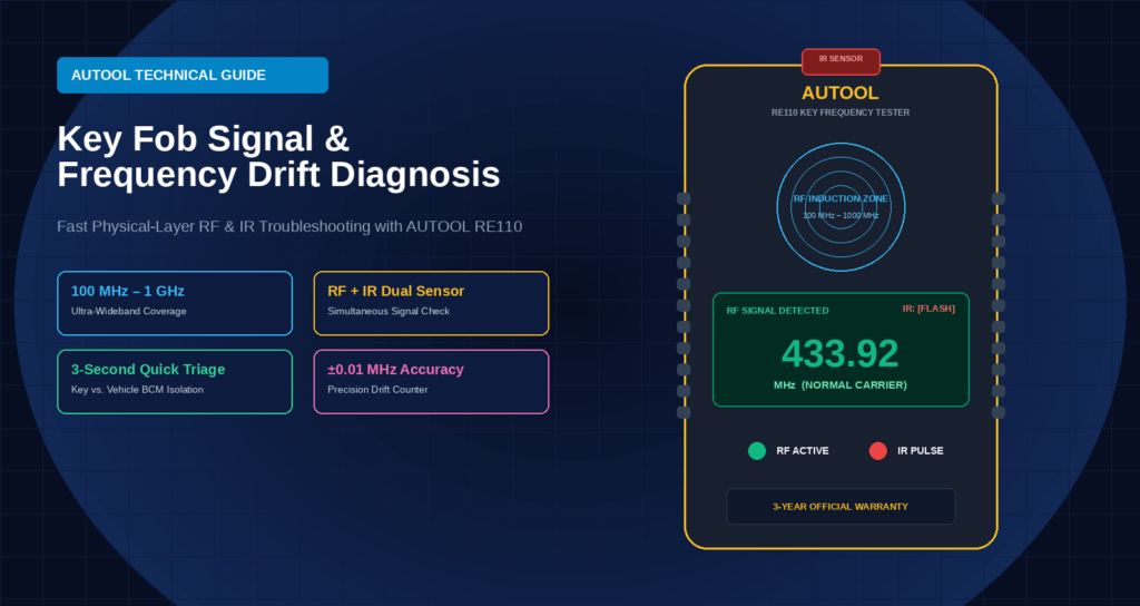
In modern automotive anti-theft systems, Remote Keyless Entry (RKE) and Passive Keyless Entry (PKE) have become standard features across a wide range of vehicles.
However, as the global radio spectrum becomes increasingly crowded and vehicles age, failures in the physical-layer RF link of remote keys are becoming more common. Many vehicles experience remote key failures even after a brand-new CR2032 lithium-manganese battery is installed, with no response from the system. Behind these failures are complex RF characteristics and hardware aging mechanisms.
Automotive remote keys operate in internationally designated ISM (Industrial, Scientific, and Medical) license-free frequency bands. Different countries and regions have specific regulations for automotive RF frequencies, such as FCC in the US, CE in Europe, and SRRC in China:
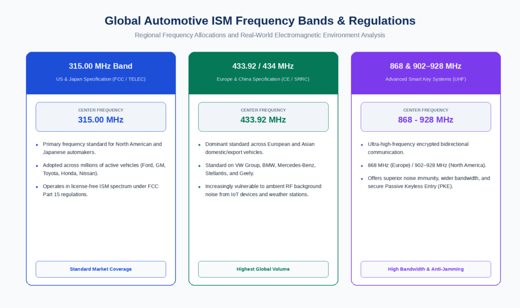
With the rapid growth of IoT devices, wireless sensors, and high-frequency communication infrastructure, background noise in automotive frequency bands has increased significantly. As a result, the RF receiver chip inside the Body Control Module (BCM) requires increasingly precise center-frequency accuracy to distinguish valid signals from interference.
A Remote Key is more than a simple button. It integrates a microcontroller (MCU), RF transmitter, crystal oscillator, and antenna/filter network.
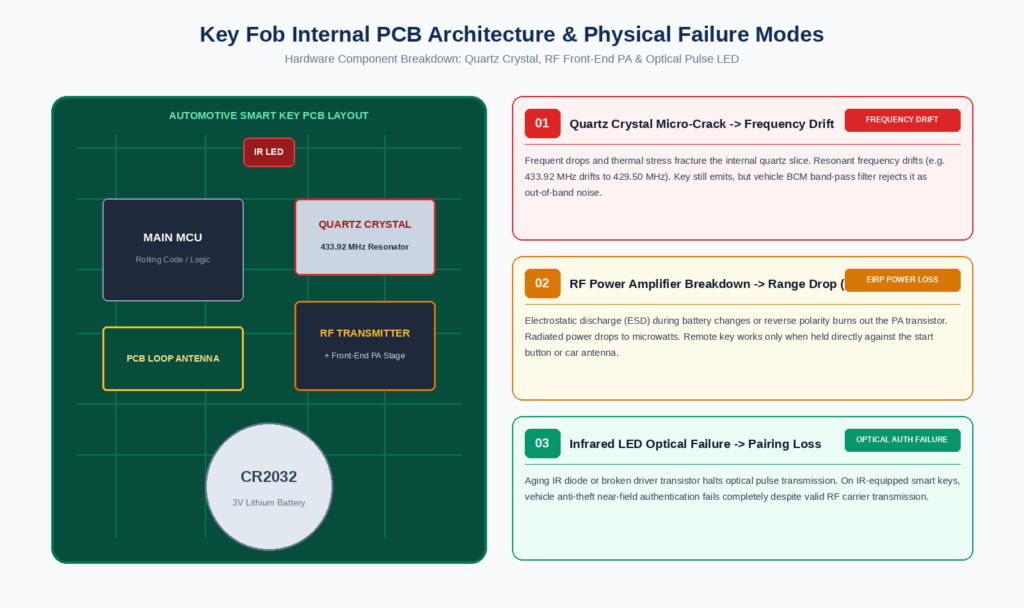
The crystal oscillator is the key component responsible for maintaining the Remote Key’s transmission frequency. Frequent drops, impacts, or temperature fluctuations can cause micro-cracks or electrode damage in the quartz crystal, resulting in frequency drift.
Electrostatic discharge (ESD) or reverse battery installation can instantly damage the RF power amplifier circuit. Although the Remote Key may still respond to button presses, its Effective Isotropic Radiated Power (EIRP) can drop significantly, reducing the effective communication range from around 30 meters to less than 5 centimeters.
In certain vehicle models, such as some early anti-theft systems and specific smart keys, the Remote Key may transmit RF signals while simultaneously sending pulse codes through an IR LED for near-field anti-theft authentication.
An aging IR LED or damaged driver transistor can cause the anti-theft authentication handshake to fail.
During routine repairs, technicians can encounter significant blind spots when diagnosing wireless signal problems:
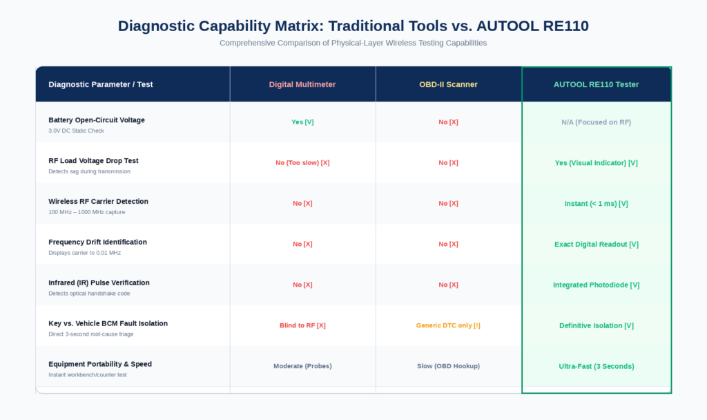
The AUTOOL RE110 Automotive Remote Key Frequency Tester is designed to address this diagnostic gap in wireless RF links, providing intuitive signal information through hardware-level detection.
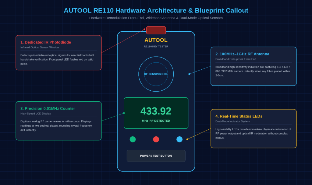
The RE110 features a wideband receiving antenna and broadband detection circuit, covering a measurement range of 100 MHz to 1 GHz (1000 MHz). It can capture signals from various remote keys, including common 315 MHz, 433 MHz, 868 MHz, and 902 MHz models, as soon as the Remote Key enters the sensing range.
The RE110 integrates a high-speed signal-shaping circuit and a precision frequency counter. It converts weak RF signals into digital frequency readings with millisecond-level response and displays measurements to two decimal places, helping technicians quickly identify frequency drift.
A dedicated infrared photodiode sensor is integrated into the top of the device to detect IR pulses from the Remote Key. This enables combined verification of RF signal transmission and IR optical signals, providing a more complete diagnostic reference.
During testing, the AUTOOL RE110 provides screen feedback that can help technicians establish a standardized fault diagnosis process:
Detection Reading & Indicator | Physical-Layer Status Analysis | Fault Determination & Repair Path |
Standard frequency (error < ±0.5 MHz) | RF carrier is normal with no significant frequency drift | Remote Key hardware is normal. The fault may be in the vehicle antenna, BCM module, or anti-theft pairing. |
Significant frequency drift (error > ±2.0 MHz) | Crystal oscillator may be physically damaged or the trimmer capacitor may have failed | Remote Key RF hardware may be damaged. Crystal replacement or Remote Key replacement/matching may be required. |
No frequency response / no reading on screen | RF circuit may be open, MCU may not be oscillating, or the micro-switch may have failed | Replace the battery first. If there is still no response, check the micro-switch continuity and power circuit. |
RF normal, IR indicator not flashing | IR LED may be open or the driver stage may have a poor solder connection | For IR-equipped models, inspect and repair the IR transmitter circuit at the Remote Key front end. |
As automotive electronic anti-theft systems become increasingly sophisticated, diagnostics need to move beyond blind trial and error toward precise physical-layer fault identification.
The AUTOOL RE110 Automotive Remote Key Frequency Tester uses wideband RF signal detection and digital frequency measurement to make otherwise invisible RF signals easier to diagnose. It helps technicians identify potential Remote Key faults more efficiently, reducing misdiagnosis and unnecessary repairs.
For complete technical specifications and parameter information for the AUTOOL RE110, please visit: