Repair testing / 8 sub-categories
Automotive Repair & Testing Equipment
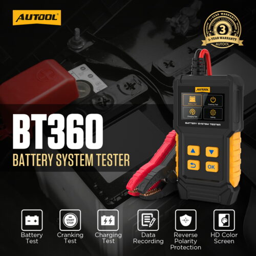
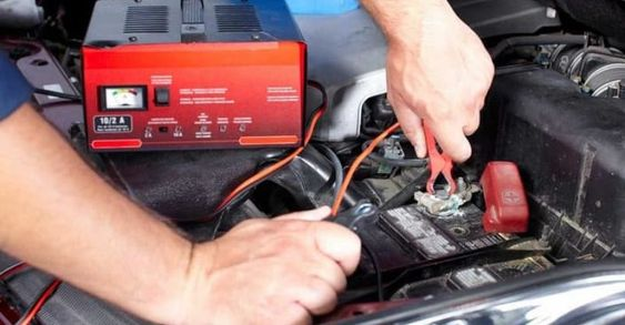
Diagnostic tools for leak tracing, visual inspection, battery health, circuits, pressure, spark, oil, and electrical readings.
Repair maintenance / 6 sub-categories
Automotive Repair & Maintenance Equipment
Service equipment for fluid exchange, A/C diagnostics, refrigerant recovery, oil handling, and cooling-system work.
Carbon cleaning / 3 sub-categories
Carbon Deposit Cleaning Equipment
Carbon-removal equipment for injectors, intake valves, components, and workshop cleaning jobs.
Wheel tire / 3 sub-categories
Wheel and Tire Repair Equipment
Equipment for alignment, lifting, tire repair, tire mounting, and service-bay workflows.
Tool storage / 1 sub-category
Workshop Tool Storage Series
Storage products for keeping workshop tools, test equipment, and accessories organized.
EV charging / 1 sub-category
Electric Vehicle Charger Series
EV charging products for new-energy vehicle service, workshop use, and installation scenarios.
OBD diagnosis / 4 sub-categories
OBD Diagnostic Tools
OBD-related testers, cable products, used-car inspection tools, and key frequency diagnostics.
Accessories / 8 sub-categories
Accessories
Replacement parts, adapters, consumables, cables, and add-ons for major diagnostic and service equipment.