
ภาษาและสกุลเงิน
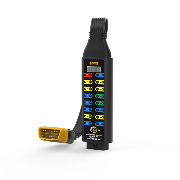
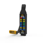
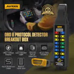

AUTOOL กล่องแปลงสัญญาณ OBD2 ที่ได้รับการอัพเกรด
US$109.00
Key Features
- Selected-Point Voltage Display
- Color-Coded Pin LEDs
- 16-Pin Test Access
- 12 V Temporary ECU Backup
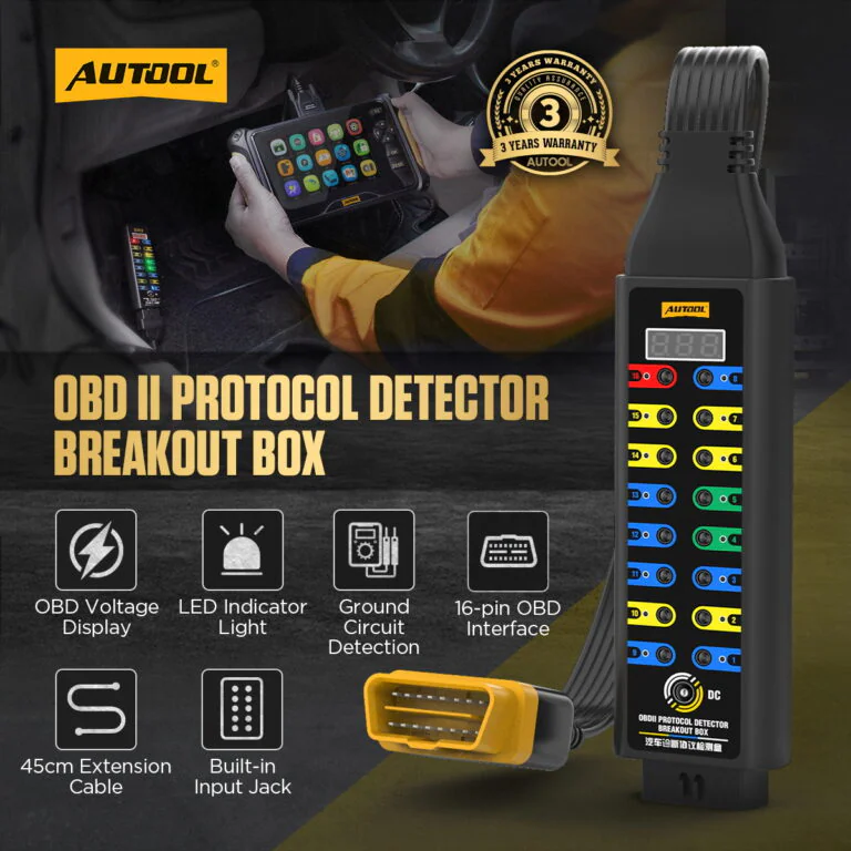
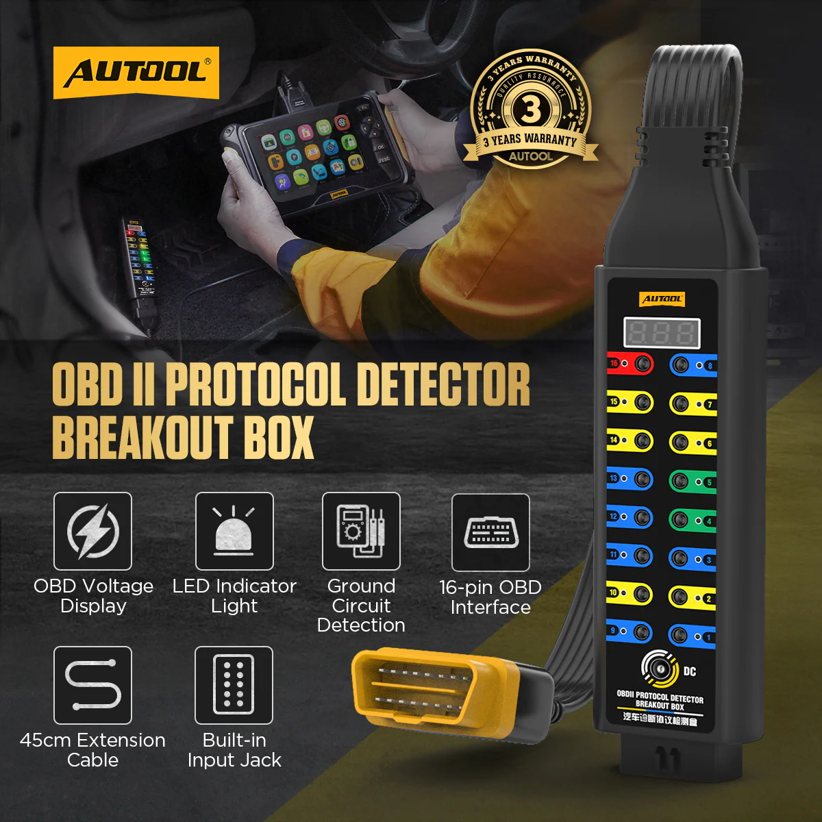
- Selected-Point Voltage Display: View the selected OBD interface voltage on the built-in display.
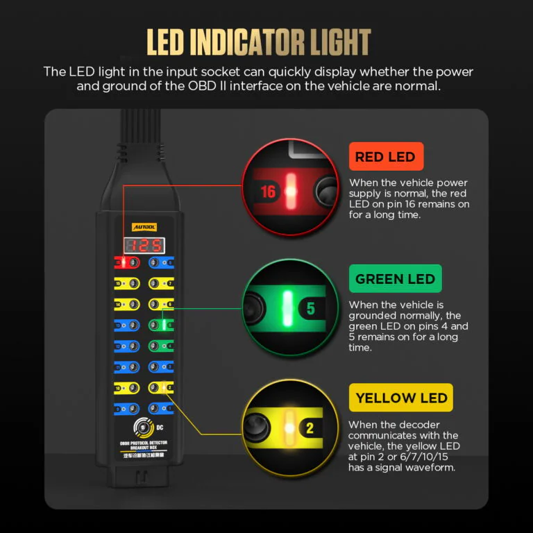
- Color-Coded Pin LEDs: Use red pin-16 power, green pin-4/5 ground, and yellow communication LEDs as status cues.
- 16-Pin Test Access: Reach all 16 OBD2 pin access points with 4 mm leads, a multimeter, or an oscilloscope while the scanner remains connected.
- 12 V Temporary ECU Backup: Use a suitable backup battery only for an approved vehicle procedure; external load devices must not exceed 1 A.
- สายเคเบิล TPU ยาว 45 ซม.: Move the test point away from the vehicle port with the 45 cm flexible TPU cable.
- 3- รับประกันปี ตัวเครื่องหลัก 3 ปี · อุปกรณ์เสริม 1 ปี
- 90-Day Returns สินค้าที่ส่งคืนต้องอยู่ในสภาพสมบูรณ์ภายใน 90 วัน
- ร้านค้าอย่างเป็นทางการ สินค้าแท้ · การสนับสนุนโดยตรง
OBD2 Breakout Box Upgraded · Voltage Display, LED Cues & 16-Pin Access
Add Voltage and LED Cues to Pin Access
Keep a compatible scanner inline while viewing selected-point voltage, reading color-coded LED state cues, and accessing all 16 DLC pins with a multimeter, oscilloscope, or compatible 4 mm leads. The Upgraded breakout box also provides an external input for approved temporary ECU backup procedures.
- 16-Pin DLC Breakout
- Selected-Point Voltage Display
- Color-Coded LED Cues
- 12 V Temporary Input
- การเชื่อมต่อขนาด 45 ซม.
Key Features
View Selected Voltage and Access All 16 Pins
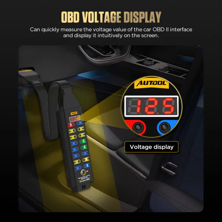
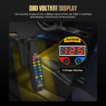
การแสดงผลแรงดันไฟฟ้า OBD
Select an OBD interface point and view its live voltage on the built-in display.
Compare the value with the correct pin, reference point, vehicle state, and a suitable meter before judging the circuit.
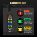
ไฟ LED แสดงสถานะ
Use red for pin 16 power, green for pins 4/5 ground, and yellow for communication-line activity cues.
Treat each LED as a connection or activity cue, then verify voltage, loaded ground, waveform, and protocol behavior with the correct diagram and instrument.
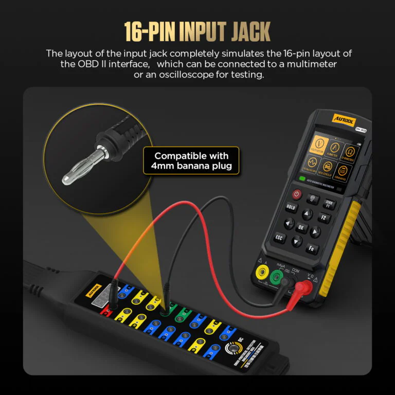
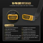
16-Pin Input Jack
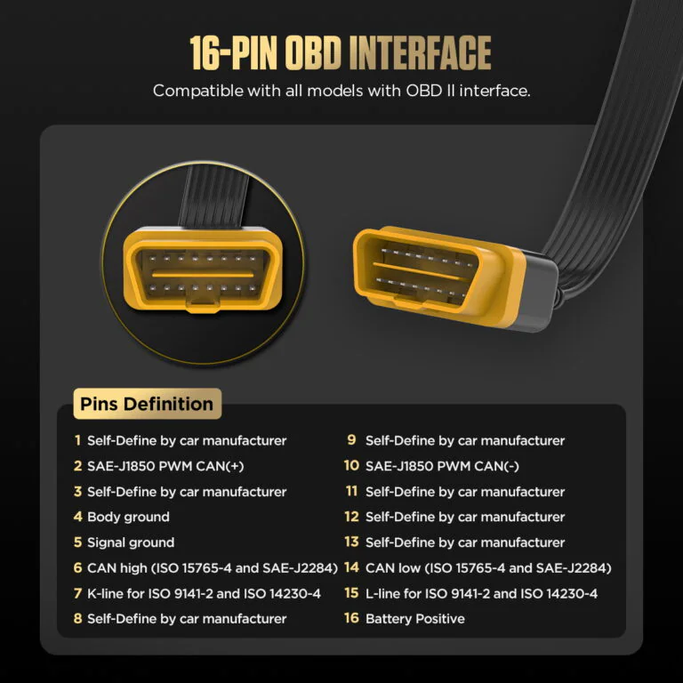
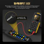
The built-in input jack fully emulates the OBDII 16-pin layout and can be used with a 4mm banana plug, multimeter or oscilloscope for pin-level testing.
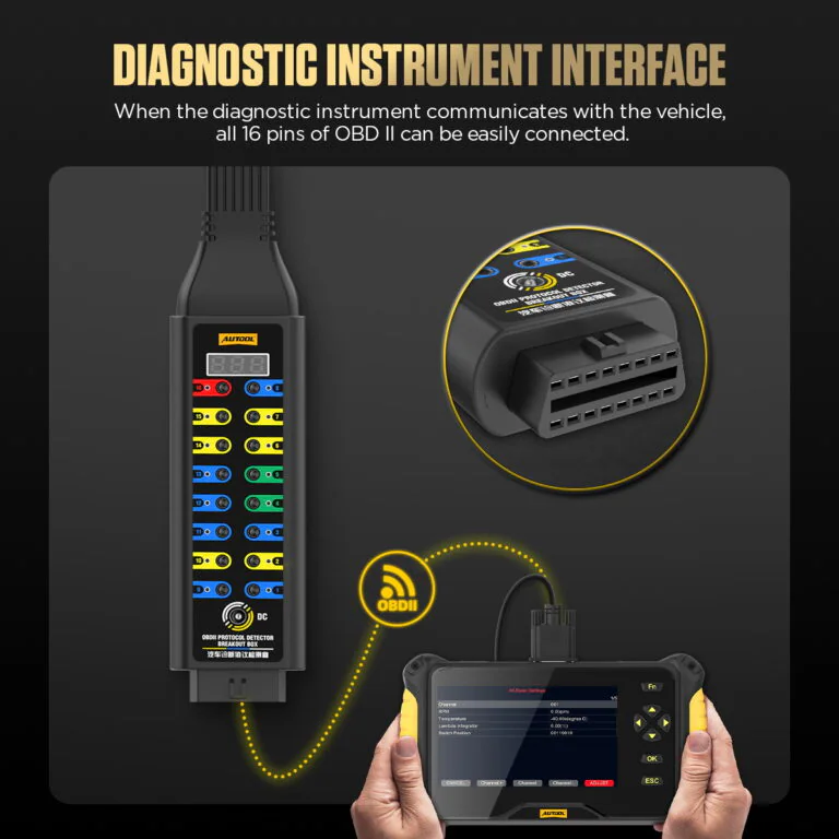
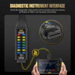
Diagnostic Instrument Interface
When the diagnostic instrument communicates with the vehicle, the breakout box allows quick access to the OBD2 16 pins for monitoring and diagnosis.
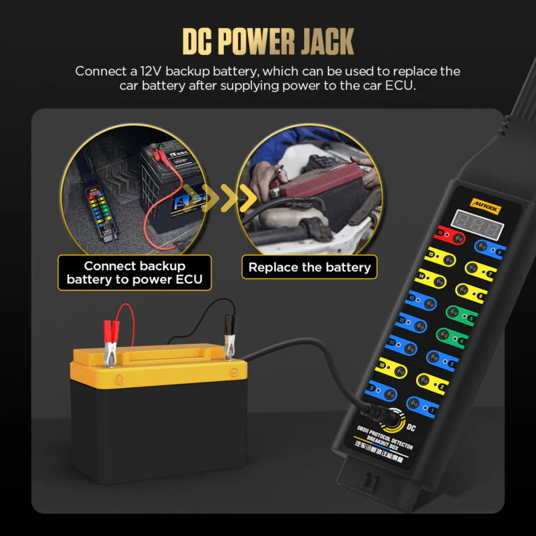
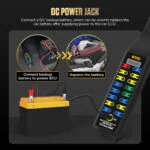
แจ็คไฟ DC
The DC interface can connect to a 12V backup battery, helping supply temporary ECU power and support battery replacement or ECU power maintenance scenarios.
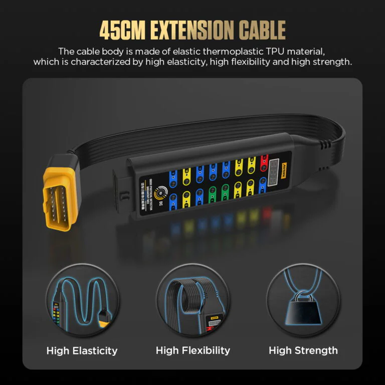
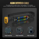
45cm TPU Extension Cable
The 45cm TPU cable is designed with high elasticity, high flexibility and high strength for easier use around vehicle OBD2 ports.
Voltage and LED Readings
Status LEDs show power, ground, or line activity only. Use the correct diagram and instrument to identify voltage, waveform, bus state, and root cause.
รับประกัน 3 ปี
ตัวเครื่องหลัก: รับประกัน 3 ปี อุปกรณ์เสริมมาตรฐาน: รับประกัน 1 ปีนโยบายการรับประกัน
วิธีใช้
เชื่อมต่อเครื่องสแกนและเครื่องมือทดสอบภายนอก
ความคืบหน้าทีละขั้นตอน1 / 5
01
Identify The Circuit
ใช้แผนผังวงจรไฟฟ้าของรถยนต์ที่ถูกต้องเพื่อระบุหน้าที่ของขา DLC แรงดันไฟฟ้าที่คาดหวัง กราวด์ เครือข่าย และวิธีการทดสอบที่ปลอดภัย
02
ตรวจสอบและเชื่อมต่อ
เมื่อรถอยู่ในสภาพที่ต้องการแล้ว ให้ตรวจสอบ DLC และเชื่อมต่อกล่องแยกสัญญาณโดยไม่ต้องฝืนหรือดันขาพินกลับเข้าไป
03
ตรวจสอบไฟและสายดิน
ตรวจสอบการจ่ายไฟและการต่อลงดินของขั้วต่อด้วยมิเตอร์ที่เหมาะสมก่อนที่จะตีความกิจกรรมการสื่อสาร
04
สังเกตและวัดผล
ควรต่อเครื่องสแกนเข้ากับสายเมื่อจำเป็น และใช้แจ็คทดสอบร่วมกับมัลติมิเตอร์หรือออสซิลโลสโคปที่เหมาะสม
05
บันทึกผลลัพธ์
บันทึกสถานะรถยนต์, รหัสพิน, ค่าอ้างอิง, แรงดันไฟฟ้าหรือรูปคลื่น, ผลการสแกน และการเปลี่ยนแปลงใดๆ เมื่อถอดกล่องออก
ความปลอดภัยและความเข้ากันได้
ตรวจสอบแรงดันไฟฟ้า โหลด และการเชื่อมต่อขาพิน
การทดสอบระดับพินที่ผ่านการรับรอง
การต่อสายจัมเปอร์ที่ไม่ถูกต้อง การป้อนไฟย้อนกลับ โหลด หรือการเชื่อมต่อโพรบที่ไม่ถูกต้อง อาจทำให้เครือข่ายและโมดูลของรถยนต์เสียหายได้
ไม่มีการขายชอร์ตโดยตรง
ห้ามต่อขา 16 เข้ากับขา 4 หรือ 5 โดยตรง หรือต่อเชื่อมแจ็คทดสอบที่ไม่ทราบชนิดเข้าด้วยกัน
ขีดจำกัดภาระภายนอก
อุปกรณ์ที่ใช้โหลดภายนอกต้องมีขนาดไม่เกิน 1 แอมป์
การตีความ LED
Use each LED as a quick supply, ground or activity cue, then use the circuit reference and diagnostic instrument for protocol or ECU checks.
พลังงานสำรอง
Use the 12 V temporary backup function only with confirmed circuit compatibility, polarity and the approved service procedure.
No 120 Ω Mode
Upgraded version does not include the switchable 120 Ω series-resistor mode.
การดูแลและบำรุงรักษา
This product connects directly to the vehicle data link, so read the safety notes before using jumpers, load devices, multimeters, oscilloscopes, or ECU backup power. Improper use may damage data communication, related circuits, or vehicle systems; stop immediately if the effect of an operation is uncertain.
ผลสอบ
Turn Pin Access into Measured Evidence
พลังงานและสายดิน
บันทึกผลการวัดแรงดันไฟเลี้ยงและแรงดันตกคร่อม/แรงดันกราวด์ ภายใต้ภาระและสภาวะของยานพาหนะที่กำหนดไว้
กิจกรรมการสื่อสาร
ใช้ไฟ LED เป็นตัวระบุตำแหน่ง จากนั้นบันทึกรูปคลื่นหรือพฤติกรรมการสแกนที่เกี่ยวข้องก่อนที่จะสรุปผล
การเปรียบเทียบการส่งผ่าน
เปรียบเทียบการสื่อสารของเครื่องสแกนเนอร์ระหว่างการเชื่อมต่อโดยตรงและการใช้กล่องแยกสัญญาณเพื่อตรวจจับการเปลี่ยนแปลงที่เกิดจากการตั้งค่า
การวินิจฉัยเครือข่าย
การตีความค่าความต้านทาน แรงดันไบแอส รูปคลื่น การสิ้นสุด และการแยกโมดูล ต้องทำผ่านขั้นตอนเครือข่ายเฉพาะสำหรับรถแต่ละคันเท่านั้น
เปรียบเทียบรุ่น
เลือกคุณสมบัติการเข้าถึง การแสดงผล และตัวบ่งชี้
คู่มือรุ่น
Choose one or more models. Upgraded Version is selected by default.
เลือก 1 รุ่น
ยังไม่ได้เลือกโมเดล โปรดเลือกโมเดลเพื่อเปรียบเทียบ
| ชื่อสินค้า | เวอร์ชั่นพื้นฐาน | ปรับรูปแบบ | เวอร์ชันพรีเมียม |
|---|---|---|---|
| ข้อจำกัดการเชื่อมต่อและการใช้งาน | |||
| พอร์ตการวินิจฉัย | OBD2 | OBD2 | OBD2 |
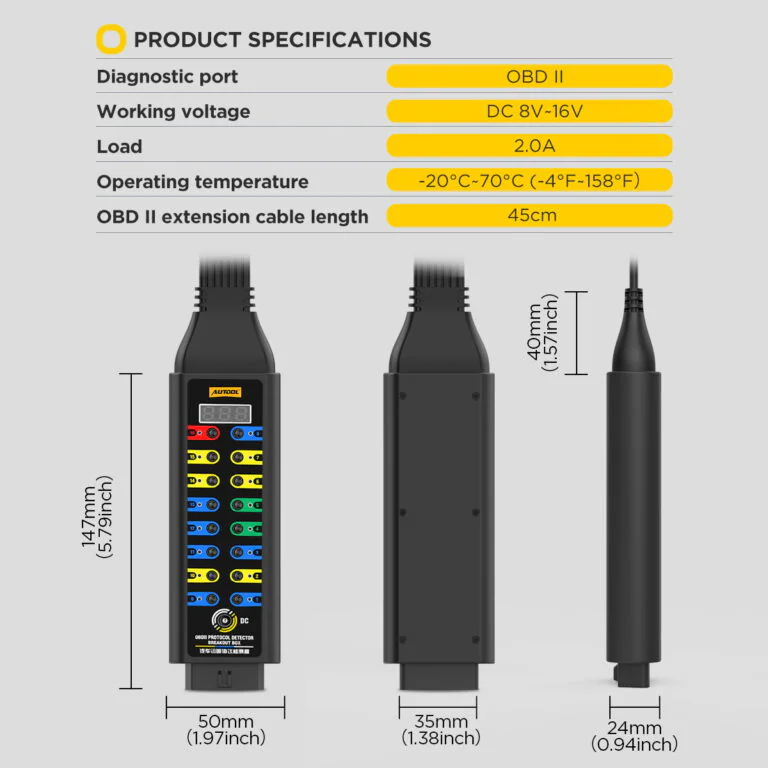
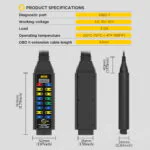
| การทำงานแรงดันไฟฟ้า | DC 8V ~ 30V | DC 8V ~ 16V | DC-6V 30V |
| โหลด | พิกัดกระแส 2.0 A; โหลดภายนอกต้องไม่เกิน 1 A | พิกัดกระแส 2.0 A; โหลดภายนอกต้องไม่เกิน 1 A | พิกัดกระแส 2.0 A; โหลดภายนอกต้องไม่เกิน 1 A |
| อุณหภูมิในการทำงาน | -20℃~70℃(-4°F~158°F) | -20℃~70℃(-4°F~158°F) | -20℃~70℃(-4°F~158°F) |
| สายต่อขยาย OBD2 ความยาว | 45CM | 45CM | 45CM |
| ฮาร์ดแวร์จอแสดงผลและพลังงาน | |||
| การแสดงผลแรงดันไฟฟ้า OBD | × | ✓ | ✓ |
| ไฟ LED แสดงสถานะ | × | ✓ | ✓ |
| สายไฟ | × | ✓ | ✓ |
| ช่องเสียบอินพุตในตัว | ✓ | ✓ | ✓ |
| ทดสอบการเข้าถึงและการตรวจสอบวงจร | |||
| การทดสอบสัญญาณโปรโตคอลการเข้าถึง | ✓ | ✓ | ✓ |
| การตรวจจับพลังงาน | ✓ | ✓ | ✓ |
| การตรวจจับวงจรลงดิน | ✓ | ✓ | ✓ |
| อินเทอร์เฟซ OBD 16 พิน | ✓ | ✓ | ✓ |
| โหมดตัวต้านทานอนุกรม 120Ω | × | × | ✓ |
คู่มือและฝ่ายสนับสนุน
ตรวจสอบพอร์ต พินเอาต์ และความพอดีของเครื่องมือ
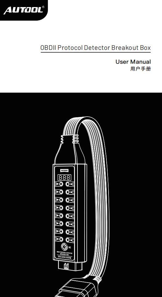
AUTOOL OBD2 Breakout Box Upgraded User Manual
Open the PDF manual for Upgraded breakout-box connection, voltage display, LED cues and pin testing, with measurement safety and troubleshooting support.
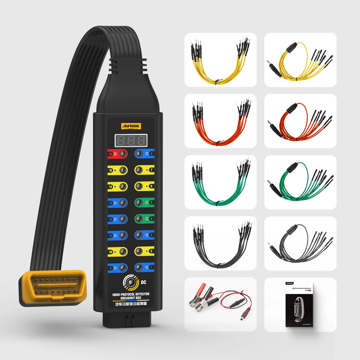
บรรจุภัณฑ์
Check the Upgraded Breakout Box Package
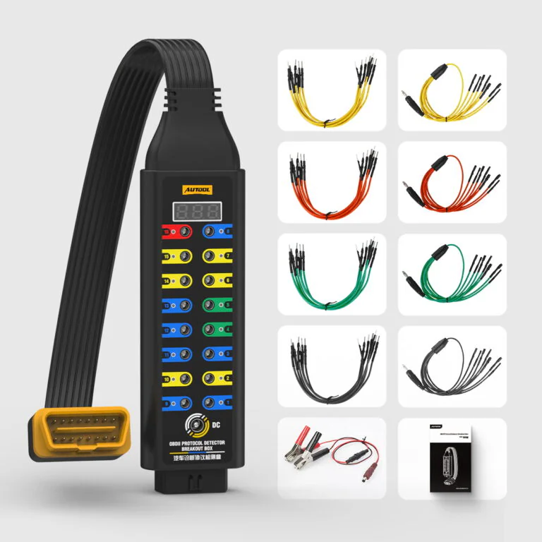
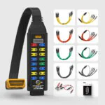
- Upgraded Breakout BoxMain device and 45 cm diagnostic connection.
- อุปกรณ์ห้องน้ำในชุดประกอบด้วยเฉพาะสายนำไฟฟ้า สายไฟ และเอกสารประกอบตามรุ่นที่เลือกเท่านั้น โปรดยืนยันตัวเลือกก่อนสั่งซื้อ
คำถามที่พบบ่อย
Upgraded OBDII Breakout Box Fit and Function Questions
What Is An OBD2 Breakout Box Used For?
An OBD2 breakout box provides access to the OBD2 diagnostic link connector so users can monitor power, ground, protocol signals and voltage, while also making it easier to connect a diagnostic tool, multimeter or oscilloscope to the 16 OBD2 pins.
What Is The Difference Between Basic And Upgraded Version?
The Upgraded Version adds OBD voltage display, LED indicator and power cable support. The Basic Version is mainly for basic protocol, power, ground, 16-pin access and built-in input jack testing without these upgraded display and indicator functions.
Upgraded adds an OBD voltage display, LED indicators and 12 V temporary ECU backup support to the pin-access layout. Premium adds the 120 Ω mode; ask AUTOOL for the current specification and package list before purchase.
Does The Upgraded Version Support 120 Ω Series Resistor Mode?
No. The Upgraded Version does not support 120 Ω series resistor mode. The comparison chart identifies this function as a Premium Version feature.
ฉันสามารถใช้กล่องทดสอบการวินิจฉัยร่วมกับมัลติมิเตอร์หรือออสซิลโลสโคปได้หรือไม่?
Yes. The built-in input jack fully emulates the 16-pin OBDII layout and can be used with a 4mm banana plug, multimeter or oscilloscope when you understand the vehicle circuit and pin function.
What Do The LED Indicators Mean?
The red indicator shows the pin 16 supply state. The green indicators show the pin 4 and pin 5 ground states. The yellow indicators show signal activity on the related communication pins.
Use the red, green and yellow LEDs as quick cues on the identified power, ground and communication pins, then use the circuit reference and an appropriate meter or oscilloscope for measurements.
Can It Supply Power To The ECU During Battery Replacement?
Yes. The DC power jack can connect to a 12V backup battery to provide temporary ECU power support during battery replacement or related service work.
What Should I Avoid When Using This Product?
- Do not directly short-circuit pin 16, pin 4 or pin 5.
- Do not use a jumper to short-circuit the input jack if you are not sure about the vehicle electrical circuit.
- Do not connect external load devices exceeding 1A, even though the product specification image lists a 2.0A load rating.
What Vehicles Is It Compatible With?
The OBD2 Breakout Box can be adapted to vehicles with an OBD2 interface and is designed for OBDII diagnostic link connector access.
กล่อง Breakout Box เป็นเครื่องสแกนวินิจฉัยโรคหรือไม่?
ไม่ครับ มันให้ข้อมูลการเข้าถึงและสถานะต่างๆ เครื่องสแกนที่ใช้งานร่วมกันได้ มิเตอร์ ออสซิลโลสโคป ข้อมูลวงจร และวิธีการวินิจฉัยยังคงแยกต่างหาก
ยังไม่มีรีวิวร่วมแบ่งปันประสบการณ์ของคุณกับผลิตภัณฑ์นี้ก่อนใคร