
ภาษาและสกุลเงิน
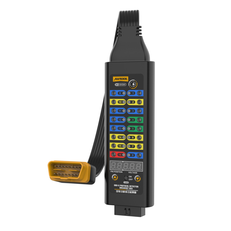
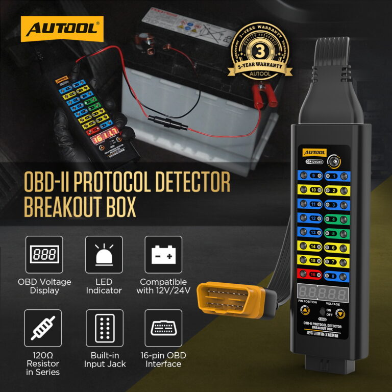
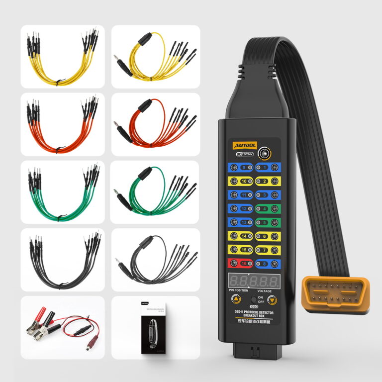
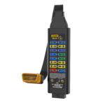
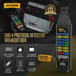
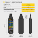
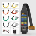
AUTOOL กล่องแปลงสัญญาณ OBD2 ระดับพรีเมียม
US$139.00
Key Features
- Inline 16-Pin Test Access
- 8–26 V Temporary ECU Power
- Selected-Pin Voltage Display
- LED Connection-State Cues
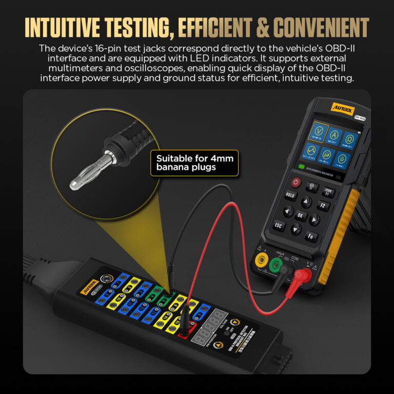
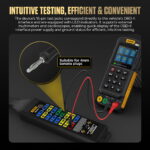
- Inline 16-Pin Test Access: Keep a compatible scanner inline and reach individual DLC pins with 4 mm leads, a multimeter, or an oscilloscope.
- 8–26 V Temporary ECU Power: Use a suitable external source only with confirmed vehicle-circuit compatibility and polarity during an approved procedure; external load devices must not exceed 1 A.
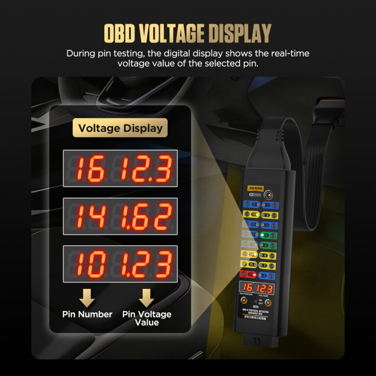
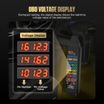
- Selected-Pin Voltage Display: View the selected OBD2 interface point and its real-time voltage on the digital display.
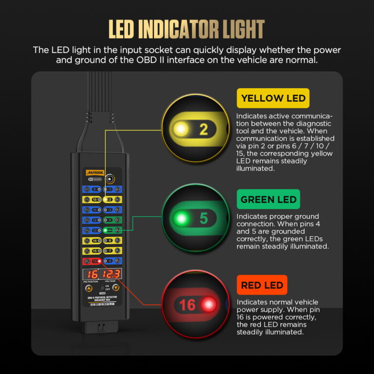
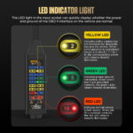
- LED Connection-State Cues: Use lit or unlit LEDs as connection-state or line-activity cues on identified pins.
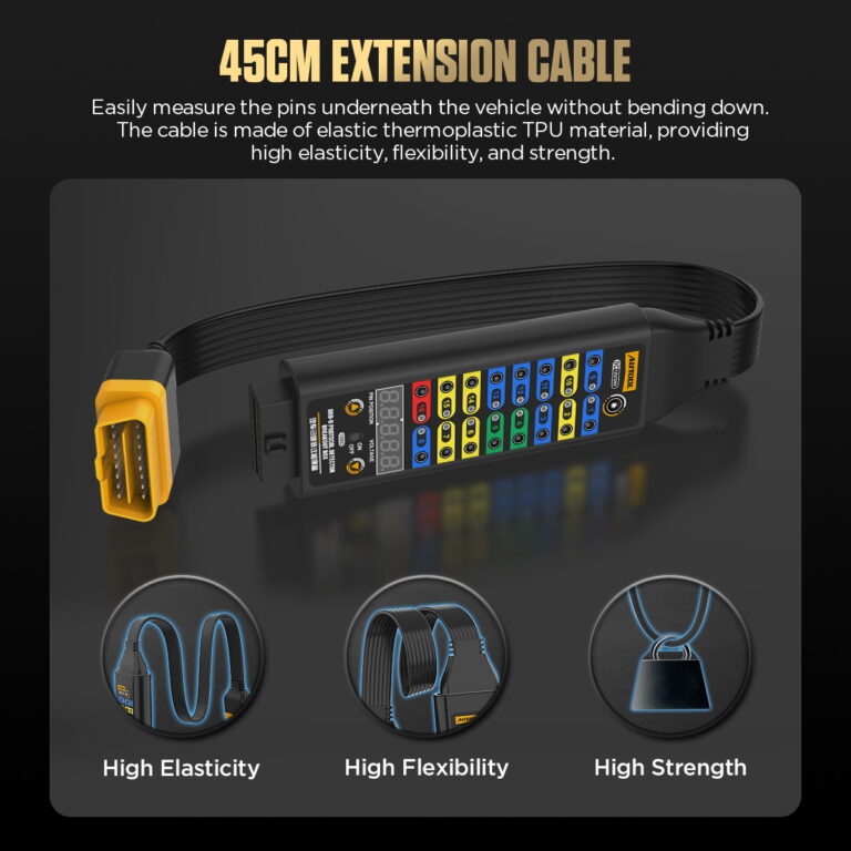
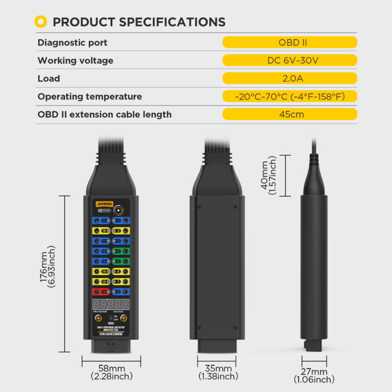
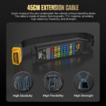
- 45 cm TPU Cable: Position the test box through its 45 cm flexible TPU diagnostic cable.
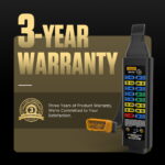
- 3- รับประกันปี ตัวเครื่องหลัก 3 ปี · อุปกรณ์เสริม 1 ปี
- 90-Day Returns สินค้าที่ส่งคืนต้องอยู่ในสภาพสมบูรณ์ภายใน 90 วัน
- ร้านค้าอย่างเป็นทางการ สินค้าแท้ · การสนับสนุนโดยตรง
OBD2 Breakout Box Premium · Voltage Display, LED Cues & 16-Pin Access
View Connection Cues and Access Every DLC Pin
Keep a compatible scanner inline while viewing selected-pin voltage, reading LED connection-state cues, and accessing all 16 DLC pins with a multimeter, oscilloscope, or compatible 4 mm leads. The Premium breakout box moves these checks to an accessible bench-style interface beside the vehicle.
- 16-Pin DLC Breakout
- Selected-Pin Voltage Display
- LED State Cues
- 4 mm External Test Access
- 45 cm Connection
Key Features
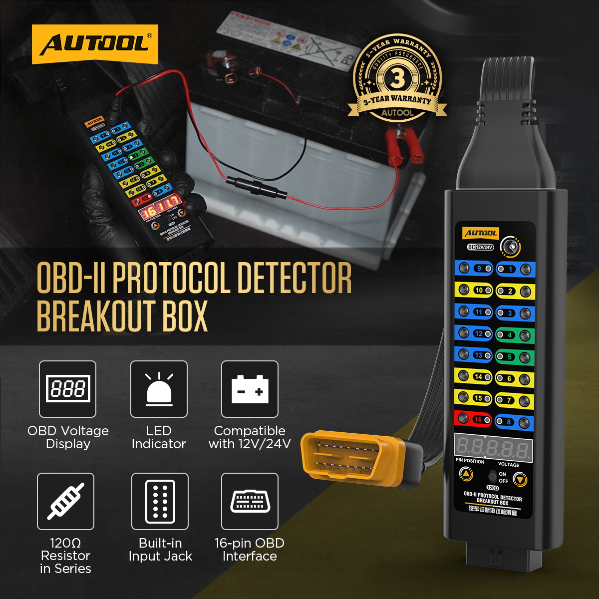
Combine Pin Access, Display and External Measurement
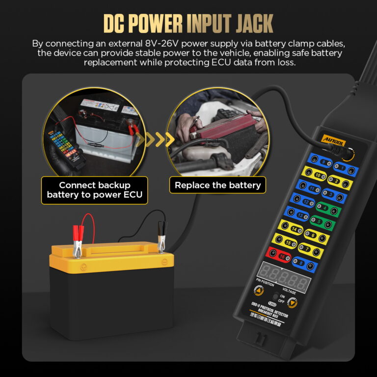
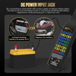
Vehicle ECU Power Supply
The external input is listed as 8–26 V for temporary ECU power support. Use it only with the exact vehicle procedure, polarity and load limits; the input does not guarantee data retention or programming stability.
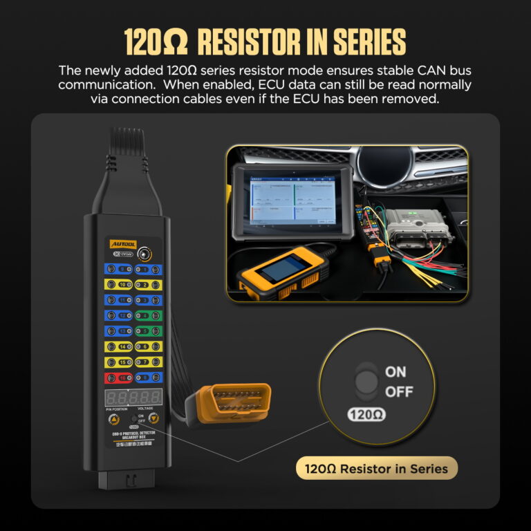
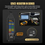
120Ω Series Resistor Mode
Use the switchable 120 Ω series-resistor mode only with the topology, insertion point and procedure specified in the delivered manual.
ฟังก์ชันไฟแสดงสถานะ LED
Use the LEDs for quick supply, ground or line-activity cues on identified OBD2 pins, then use the displayed voltage or an appropriate meter for electrical measurements.
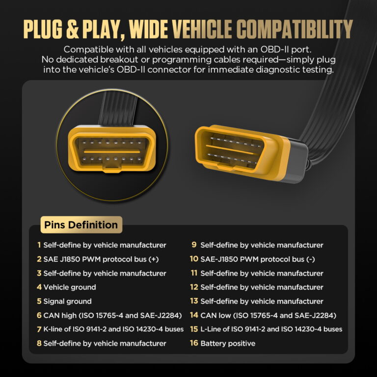
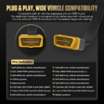
16-Pin OBD2 Connector
Compatible with vehicles featuring an OBD2 interface and provides direct diagnostic access to all 16 OBD2 pins.
45cm TPU Cable
The 45cm TPU cable offers high elasticity, flexibility, and durability for repeated workshop diagnostic use.
จอแสดงแรงดันไฟฟ้าแบบเรียลไทม์
The display shows a real-time voltage value for the selected OBD2 interface point during diagnostic checks. Compare the reading with the correct pin, reference, vehicle state, and an appropriate meter before deciding whether the circuit is within specification.
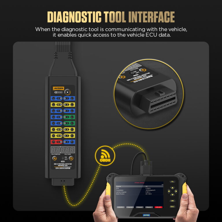
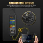
อินเทอร์เฟซการวินิจฉัย
Provides rapid breakout access to all 16 OBD2 pins during vehicle communication and line-condition checks.
Fully Analog OBD2 Interface
Compatible with multimeters and oscilloscopes for deeper signal, circuit, and diagnostic line testing.
Scanner and Test-Instrument Access
Connect the diagnostic tool through the box and access individual pins with compatible 4mm banana-plug leads, a multimeter or an oscilloscope.
Temporary ECU Power Support
Connect a suitable external power source to support ECU power during service, following the model’s voltage and load limits.
Pin Selection and Voltage Readout
The digital display identifies the selected pin and presents its voltage during circuit checks.
Measurement Boundary
Use the status LEDs as power, ground, or line-activity cues, then verify voltage, loaded ground, waveform, bus state, and root cause with the correct vehicle diagram and suitable instrument.
OBD-II Breakout Box Applications
Connect a compatible scanner, multimeter or oscilloscope through the breakout points to inspect communication and circuit conditions without repeatedly back-probing the DLC.
รับประกัน 3 ปี
ตัวเครื่องหลัก: รับประกัน 3 ปี อุปกรณ์เสริมมาตรฐาน: รับประกัน 1 ปีนโยบายการรับประกัน
วิธีใช้
Connect the Scanner and External Test Tools
ความคืบหน้าทีละขั้นตอน1 / 5
01
Identify The Circuit
Use the correct vehicle wiring diagram to identify DLC pin functions, expected voltage, ground, network, and safe test method.
02
Inspect And Connect
With the vehicle in the required state, inspect the DLC and connect the breakout box without forcing or back-feeding pins.
03
Check Power And Grounds
Verify connector supply and grounds with a suitable meter before interpreting communication activity.
04
Observe And Measure
Keep the scanner inline when required and use test jacks with the appropriate multimeter or oscilloscope.
05
Record The Result
Save vehicle state, pin, reference, voltage or waveform, scanner result, and any changes when the box is removed.
ความปลอดภัยและความเข้ากันได้
Check Voltage, Load and Pin Connections
Qualified Pin-Level Testing
Incorrect jumpers, back-feeding, loads, or probe connections can damage vehicle networks and modules.
No Direct Shorts
Do not directly short pin 16 to pins 4 or 5, or bridge unknown test jacks.
External Load Limit
External load devices must not exceed 1 A.
Use the LED Cues
Use each LED as a quick supply, ground or activity cue, then use the circuit reference and diagnostic instrument for protocol or ECU checks.
พลังงานสำรอง
Use external power only with a confirmed circuit and vehicle procedure; it is not a universal programming supply.
120 Ω Mode
Use the 120 Ω series-resistor mode only with the topology, insertion point and procedure specified in the delivered manual.
ข้อกำหนดด้านความปลอดภัย
This product connects directly to the vehicle data link. Improper use may damage the communication system or related circuits, so stop if the operation is not understood and do not directly short pins 16, 4, and 5.
ผลสอบ
Use External Measurements at the Pin Access Points
Power And Ground
Record measured supply and voltage-drop/ground results under the defined load and vehicle state.
กิจกรรมการสื่อสาร
Use LEDs as location cues, then capture the relevant waveform or scanner behavior before reaching a conclusion.
Pass-Through Comparison
Compare scanner communication with direct connection and with the breakout box inline to detect setup-induced changes.
การวินิจฉัยเครือข่าย
Interpret resistance, bias voltage, waveform, termination, and module isolation only through the vehicle-specific network procedure.
เปรียบเทียบรุ่น
Choose Access, Display and Indicator Features
คู่มือรุ่น
Choose one or more models. Premium Version is selected by default.
เลือก 1 รุ่น
ยังไม่ได้เลือกโมเดล โปรดเลือกโมเดลเพื่อเปรียบเทียบ
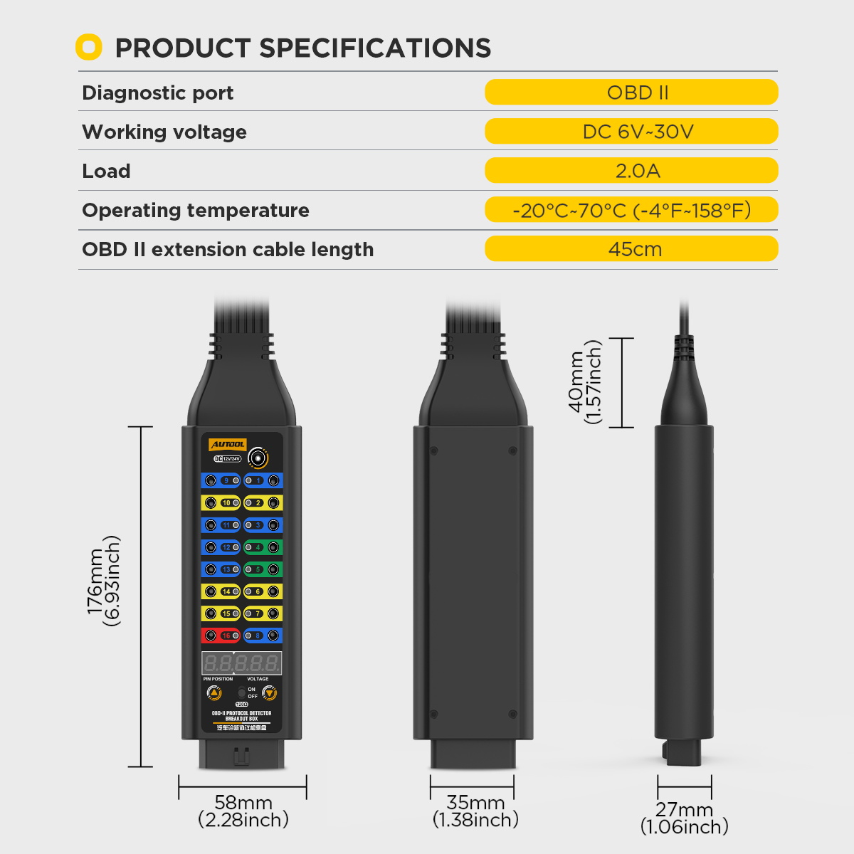
| ชื่อสินค้า | เวอร์ชั่นพื้นฐาน | ปรับรูปแบบ | เวอร์ชันพรีเมียม |
|---|---|---|---|
| Connection & Operating Limits | |||
| พอร์ตการวินิจฉัย | OBD2 | OBD2 | OBD2 |
| การทำงานแรงดันไฟฟ้า | DC 8V ~ 30V | DC 8V ~ 16V | DC-6V 30V |
| โหลด | 2.0 A rated; external load must not exceed 1 A | 2.0 A rated; external load must not exceed 1 A | 2.0 A rated; external load must not exceed 1 A |
| อุณหภูมิในการทำงาน | -20℃~70℃(-4°F~158°F) | -20℃~70℃(-4°F~158°F) | -20℃~70℃(-4°F~158°F) |
| OBD2 Extension Cable Length | 45CM | 45CM | 45CM |
| Display & Power Hardware | |||
| OBD Voltage Display | × | ✓ | ✓ |
| ไฟ LED แสดงสถานะ | × | ✓ | ✓ |
| สายไฟ | × | ✓ | ✓ |
| Built-in Input Jack | ✓ | ✓ | ✓ |
| Test Access & Circuit Checks | |||
| Protocol Signal Test Access | ✓ | ✓ | ✓ |
| การตรวจจับพลังงาน | ✓ | ✓ | ✓ |
| Ground Circuit Detection | ✓ | ✓ | ✓ |
| 16-pin OBD Interface | ✓ | ✓ | ✓ |
| 120Ω Series Resistor Mode | × | × | ✓ |
คู่มือและฝ่ายสนับสนุน
ตรวจสอบพอร์ต พินเอาต์ และความพอดีของเครื่องมือ
AUTOOL OBD2 Breakout Box Premium User Manual
Open the PDF manual for Premium breakout-box connection, voltage display, LED cues and pin testing, with measurement safety and troubleshooting support.
บรรจุภัณฑ์
Premium Breakout Box and Included Hardware
- Premium Breakout BoxMain device with a 45 cm diagnostic connection.
- อุปกรณ์ห้องน้ำOnly the leads, power cable, and documentation shown for the selected version are included; confirm the option before ordering.
คำถามที่พบบ่อย
คำถามเกี่ยวกับตัวเชื่อมต่อ ความพอดี และฟังก์ชันการทำงาน
What Is This OBD2 Breakout Box Used For?
It is used to check OBD-II communication, power, ground, and diagnostic line conditions between a vehicle and a diagnostic scanner. It also gives technicians convenient access to all 16 OBD2 pins for deeper diagnostic testing.
The box provides pass-through scanner connection, individual DLC pin access, displayed voltage and LED cues for targeted checks with a scanner, meter or oscilloscope.
What Does The External 8-26V Power Supply Do?
The page lists an external 8–26 V input for temporary power support during a defined diagnostic or service procedure. Confirm the vehicle circuit, polarity, load and required supply quality; this field does not guarantee ECU data retention or programming stability.
What Is The 120 Ω Series Mode Used For?
Before using the 120 Ω mode, confirm its topology, insertion point, switch logic and permitted procedure in the delivered manual. Do not assume it suits every nominal 60 Ω network, repairs CAN communication or makes a removed ECU readable.
Can I Use the Diagnostic Breakout Box with a Multimeter or Oscilloscope?
Yes. The fully analog OBD2 interface is compatible with multimeters and oscilloscopes, allowing deeper testing of voltage, signal, and communication line conditions.
Can I Short The OBD Pins With A Jumper?
Do not short-circuit the input jack if you are not sure about the vehicle electrical circuit. Do not directly short-circuit pin 16, pin 4, and pin 5.
Can I Connect A Load Device?
Do not use this product to connect a load device with a power exceeding 1 ampere.
Is The Breakout Box A Diagnostic Scanner?
No. It provides access and status indications. A compatible scanner, meter, oscilloscope, circuit information, and diagnostic method remain separate.
What Must Be Confirmed Before Ordering The Premium Variant?
Premium adds a voltage display, LED indicators, an 8–26 V external-input field and a 120 Ω mode. Ask AUTOOL for the current Premium specification and package list before purchase.
ยังไม่มีรีวิวร่วมแบ่งปันประสบการณ์ของคุณกับผลิตภัณฑ์นี้ก่อนใคร