
ЯЗЫК И ВАЛЮТА
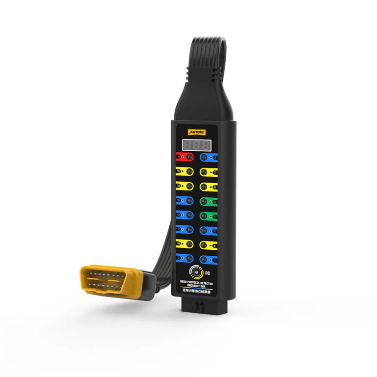
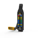
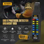
AUTOOL Усовершенствованный OBD2-адаптер
US$109.00
Ключевые особенности
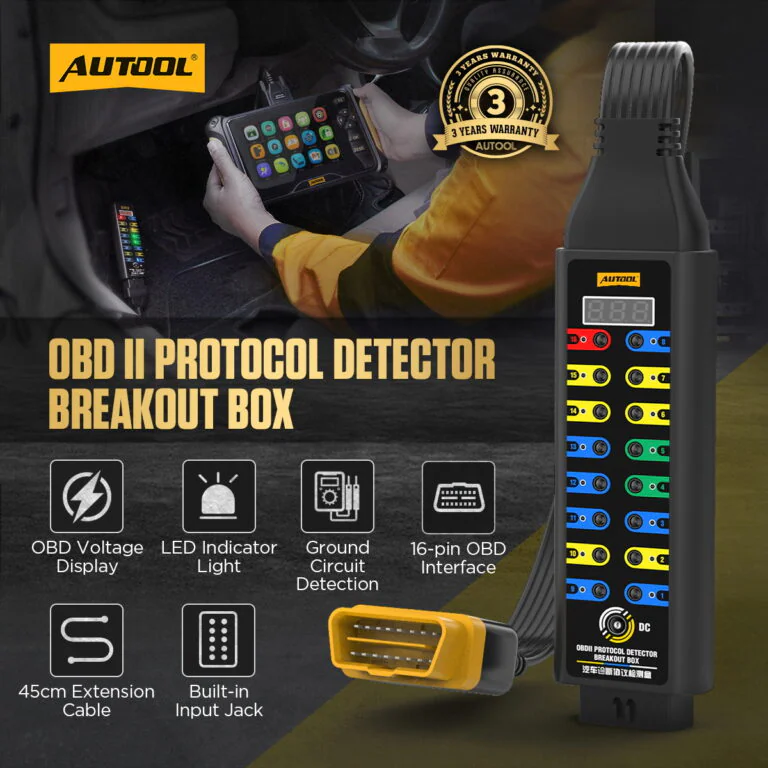
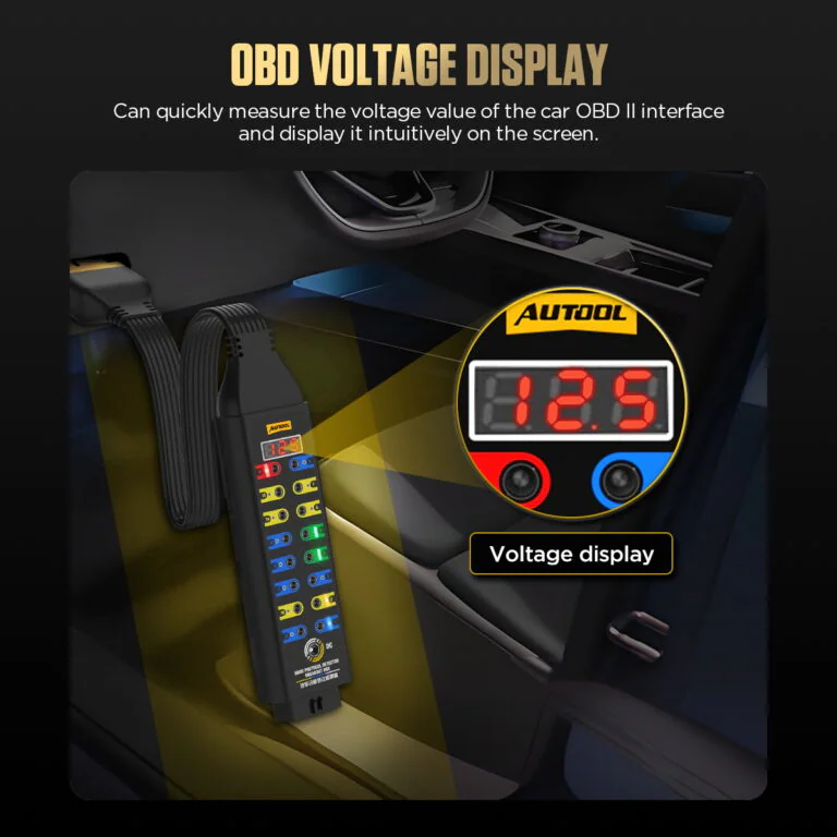
- Selected-Point Voltage Display
- Color-Coded Pin LEDs
- 16-Pin Test Access
- 12 V Temporary ECU Backup
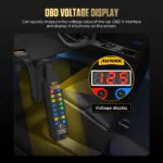
- Selected-Point Voltage Display: View the selected OBD interface voltage on the built-in display.
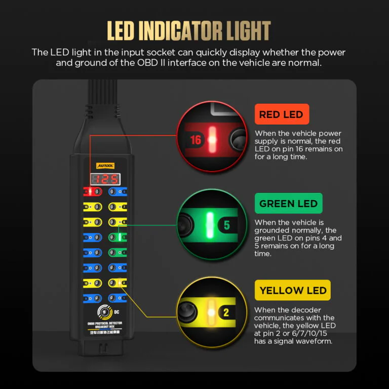
- Color-Coded Pin LEDs: Use red pin-16 power, green pin-4/5 ground, and yellow communication LEDs as status cues.
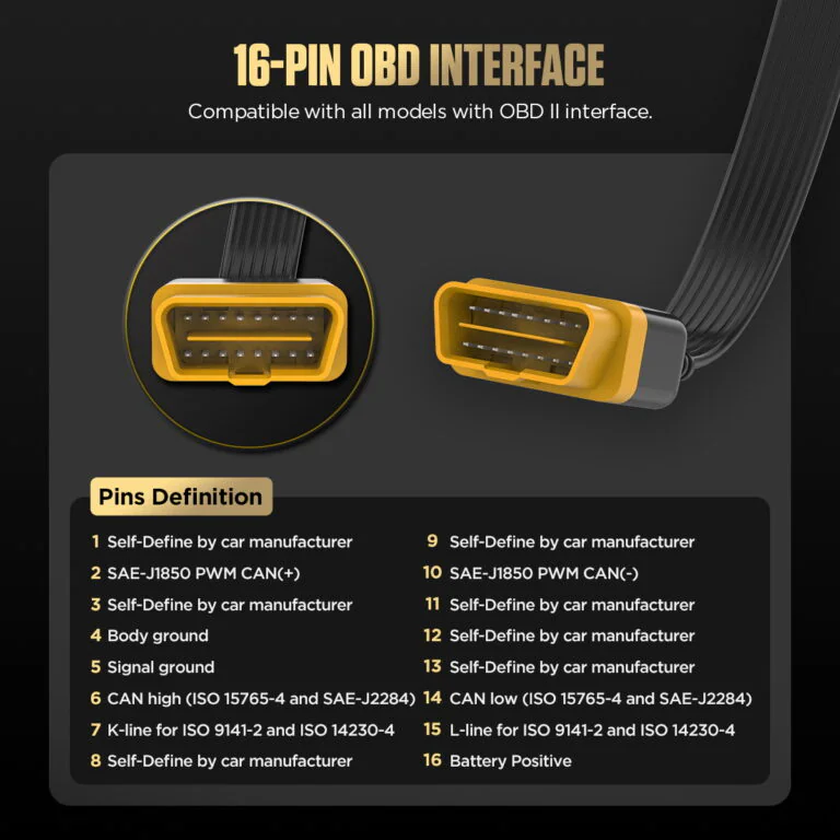
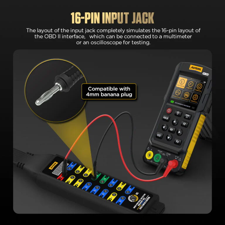
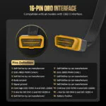
- 16-Pin Test Access: Reach all 16 OBD2 pin access points with 4 mm leads, a multimeter, or an oscilloscope while the scanner remains connected.
- 12 V Temporary ECU Backup: Use a suitable backup battery only for an approved vehicle procedure; external load devices must not exceed 1 A.
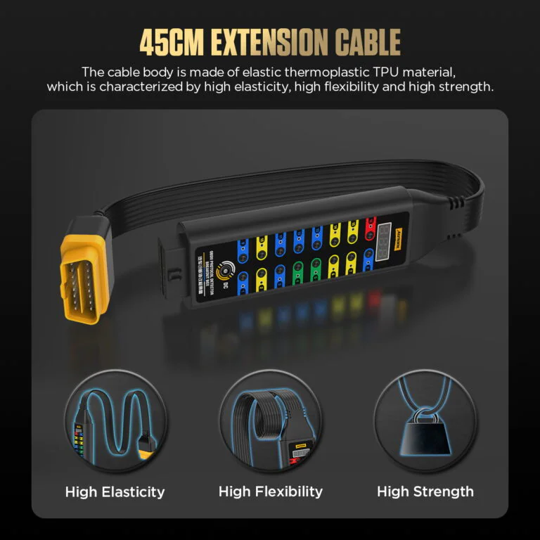
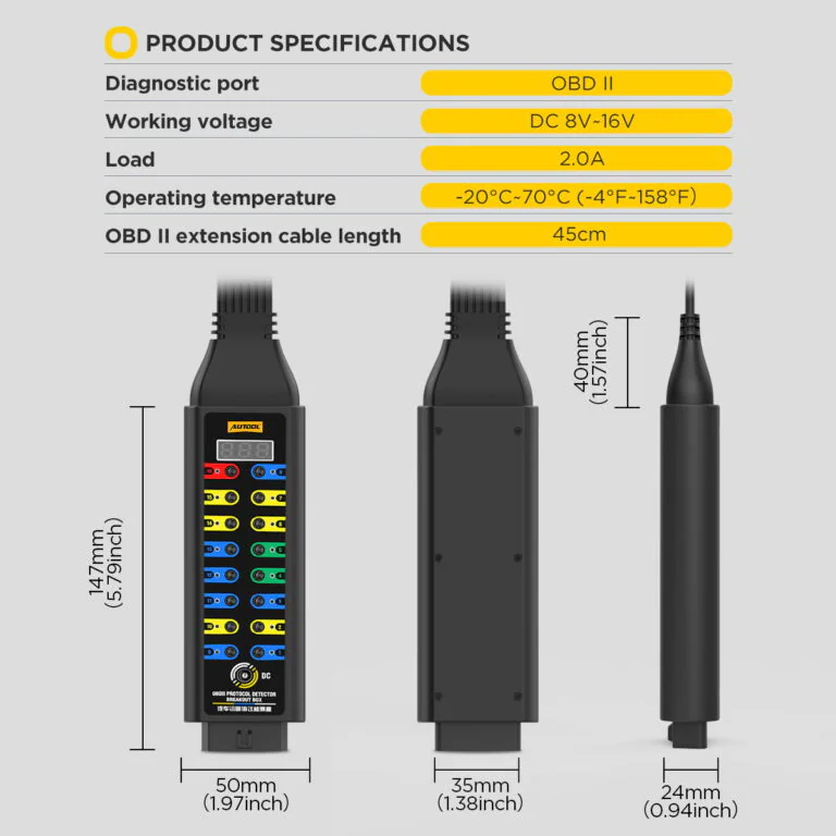
- 45 cm TPU Cable: Move the test point away from the vehicle port with the 45 cm flexible TPU cable.
☰ ЗАПРОСИТЬ ОПТОВОЕ ПРЕДЛОЖЕНИЕ / B2BОфициальный запрос на коммерческое предложение
Форма запроса на загрузку...
- 3-летнюю гарантию Основной блок: 3 года · Аксессуары: 1 год
- 90-Day Returns Возврат возможен в течение 90 дней.
- Официальный магазин Оригинальная продукция · Прямая поддержка
OBD2 Breakout Box Upgraded · Voltage Display, LED Cues & 16-Pin Access
Add Voltage and LED Cues to Pin Access
Keep a compatible scanner inline while viewing selected-point voltage, reading color-coded LED state cues, and accessing all 16 DLC pins with a multimeter, oscilloscope, or compatible 4 mm leads. The Upgraded breakout box also provides an external input for approved temporary ECU backup procedures.
- 16-Pin DLC Breakout
- Selected-Point Voltage Display
- Color-Coded LED Cues
- 12 V Temporary Input
- 45 cm Connection
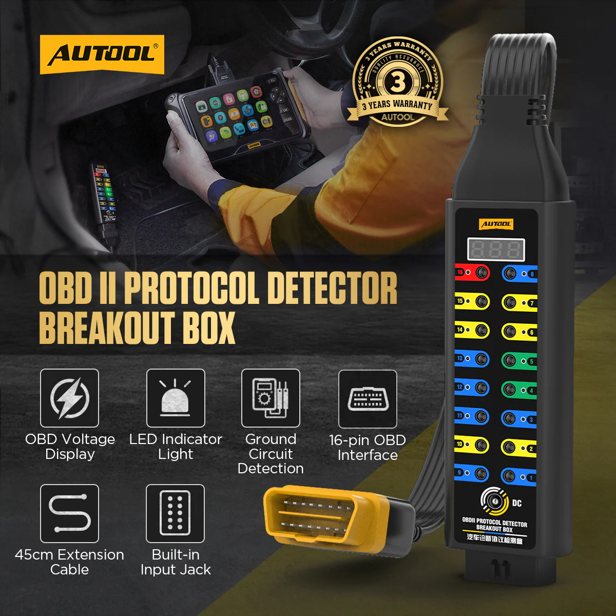
Ключевые особенности
View Selected Voltage and Access All 16 Pins
OBD Voltage Display
Select an OBD interface point and view its live voltage on the built-in display.
Compare the value with the correct pin, reference point, vehicle state, and a suitable meter before judging the circuit.
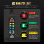
Светодиодный индикатор
Use red for pin 16 power, green for pins 4/5 ground, and yellow for communication-line activity cues.
Treat each LED as a connection or activity cue, then verify voltage, loaded ground, waveform, and protocol behavior with the correct diagram and instrument.
16-Pin Input Jack
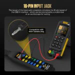
The built-in input jack fully emulates the OBDII 16-pin layout and can be used with a 4mm banana plug, multimeter or oscilloscope for pin-level testing.
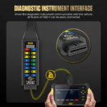
Diagnostic Instrument Interface
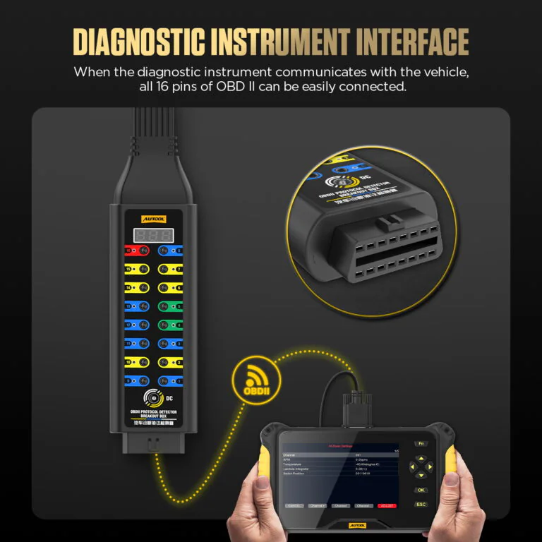
When the diagnostic instrument communicates with the vehicle, the breakout box allows quick access to the OBD2 16 pins for monitoring and diagnosis.
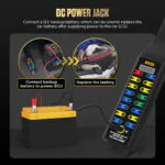
Разъем питания постоянного тока
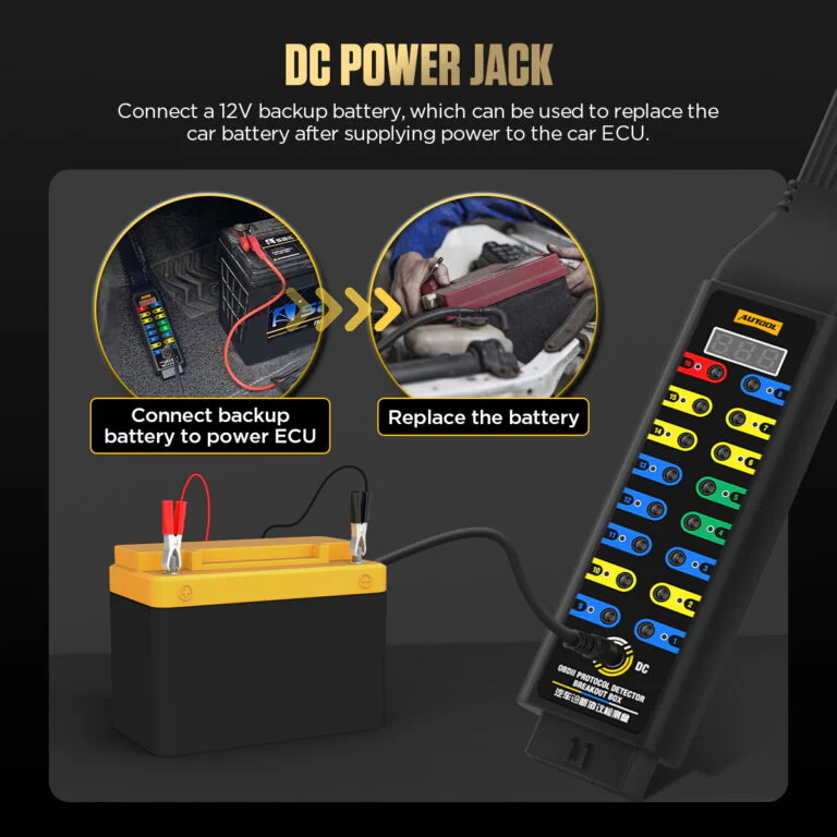
The DC interface can connect to a 12V backup battery, helping supply temporary ECU power and support battery replacement or ECU power maintenance scenarios.
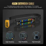
45cm TPU Extension Cable
The 45cm TPU cable is designed with high elasticity, high flexibility and high strength for easier use around vehicle OBD2 ports.
Voltage and LED Readings
Status LEDs show power, ground, or line activity only. Use the correct diagram and instrument to identify voltage, waveform, bus state, and root cause.
Гарантийное обслуживание в течение 3 лет
Основной блок: 3-летняя гарантия. Стандартные аксессуары: 1-летняя гарантия. Гарантийные условия.
Как использовать
Connect the Scanner and External Test Tools
Шаг вперед1 / 5
01
Identify The Circuit
Use the correct vehicle wiring diagram to identify DLC pin functions, expected voltage, ground, network, and safe test method.
02
Inspect And Connect
With the vehicle in the required state, inspect the DLC and connect the breakout box without forcing or back-feeding pins.
03
Check Power And Grounds
Verify connector supply and grounds with a suitable meter before interpreting communication activity.
04
Observe And Measure
Keep the scanner inline when required and use test jacks with the appropriate multimeter or oscilloscope.
05
Record The Result
Save vehicle state, pin, reference, voltage or waveform, scanner result, and any changes when the box is removed.
Безопасность и совместимость
Check Voltage, Load and Pin Connections
Qualified Pin-Level Testing
Incorrect jumpers, back-feeding, loads, or probe connections can damage vehicle networks and modules.
No Direct Shorts
Do not directly short pin 16 to pins 4 or 5, or bridge unknown test jacks.
External Load Limit
External load devices must not exceed 1 A.
Светодиодная интерпретация
Use each LED as a quick supply, ground or activity cue, then use the circuit reference and diagnostic instrument for protocol or ECU checks.
Резервное питание
Use the 12 V temporary backup function only with confirmed circuit compatibility, polarity and the approved service procedure.
No 120 Ω Mode
Upgraded version does not include the switchable 120 Ω series-resistor mode.
Уход и обслуживание
This product connects directly to the vehicle data link, so read the safety notes before using jumpers, load devices, multimeters, oscilloscopes, or ECU backup power. Improper use may damage data communication, related circuits, or vehicle systems; stop immediately if the effect of an operation is uncertain.
Результаты
Turn Pin Access into Measured Evidence
Power And Ground
Record measured supply and voltage-drop/ground results under the defined load and vehicle state.
Коммуникационная активность
Use LEDs as location cues, then capture the relevant waveform or scanner behavior before reaching a conclusion.
Pass-Through Comparison
Compare scanner communication with direct connection and with the breakout box inline to detect setup-induced changes.
Диагностика сети
Interpret resistance, bias voltage, waveform, termination, and module isolation only through the vehicle-specific network procedure.
Сравнение моделей
Choose Access, Display and Indicator Features
Руководство по модели
Choose one or more models. Upgraded Version is selected by default.
Выбрана 1 модель
Модель не выбрана. Выберите модель для сравнения.
| Наименование | Базовая версия | Модернизированная версия | Премиум версия |
|---|---|---|---|
| Connection & Operating Limits | |||
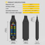
| Диагностический порт | OBD2 | OBD2 | OBD2 |
| Рабочее напряжение | DC 8V ~ 30V | DC 8V ~ 16V | DC 6V-30V |
| нагрузка | 2.0 A rated; external load must not exceed 1 A | 2.0 A rated; external load must not exceed 1 A | 2.0 A rated; external load must not exceed 1 A |
| Рабочая Температура | -20℃~70℃(-4°F~158°F) | -20℃~70℃(-4°F~158°F) | -20℃~70℃(-4°F~158°F) |
| OBD2 Extension Cable Length | 45CM | 45CM | 45CM |
| Display & Power Hardware | |||
| OBD Voltage Display | × | ✓ | ✓ |
| Светодиодный индикатор | × | ✓ | ✓ |
| Силовой кабель | × | ✓ | ✓ |
| Built-in Input Jack | ✓ | ✓ | ✓ |
| Test Access & Circuit Checks | |||
| Protocol Signal Test Access | ✓ | ✓ | ✓ |
| Обнаружение мощности | ✓ | ✓ | ✓ |
| Ground Circuit Detection | ✓ | ✓ | ✓ |
| 16-pin OBD Interface | ✓ | ✓ | ✓ |
| 120Ω Series Resistor Mode | × | × | ✓ |
Руководство и поддержка
Подтвердите соответствие порта, распиновки и инструмента.
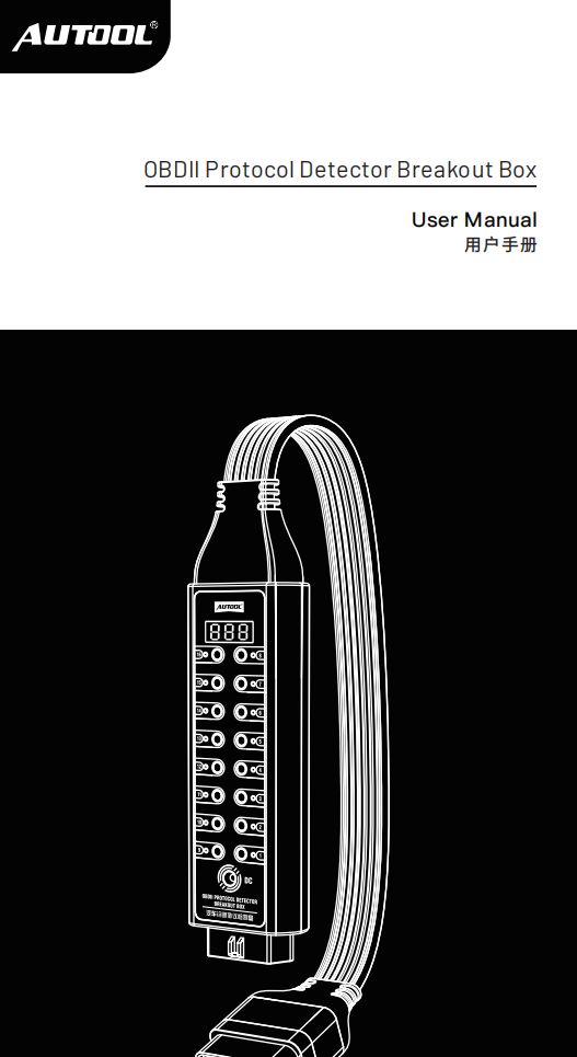
AUTOOL OBD2 Breakout Box Upgraded User Manual
Open the PDF manual for Upgraded breakout-box connection, voltage display, LED cues and pin testing, with measurement safety and troubleshooting support.
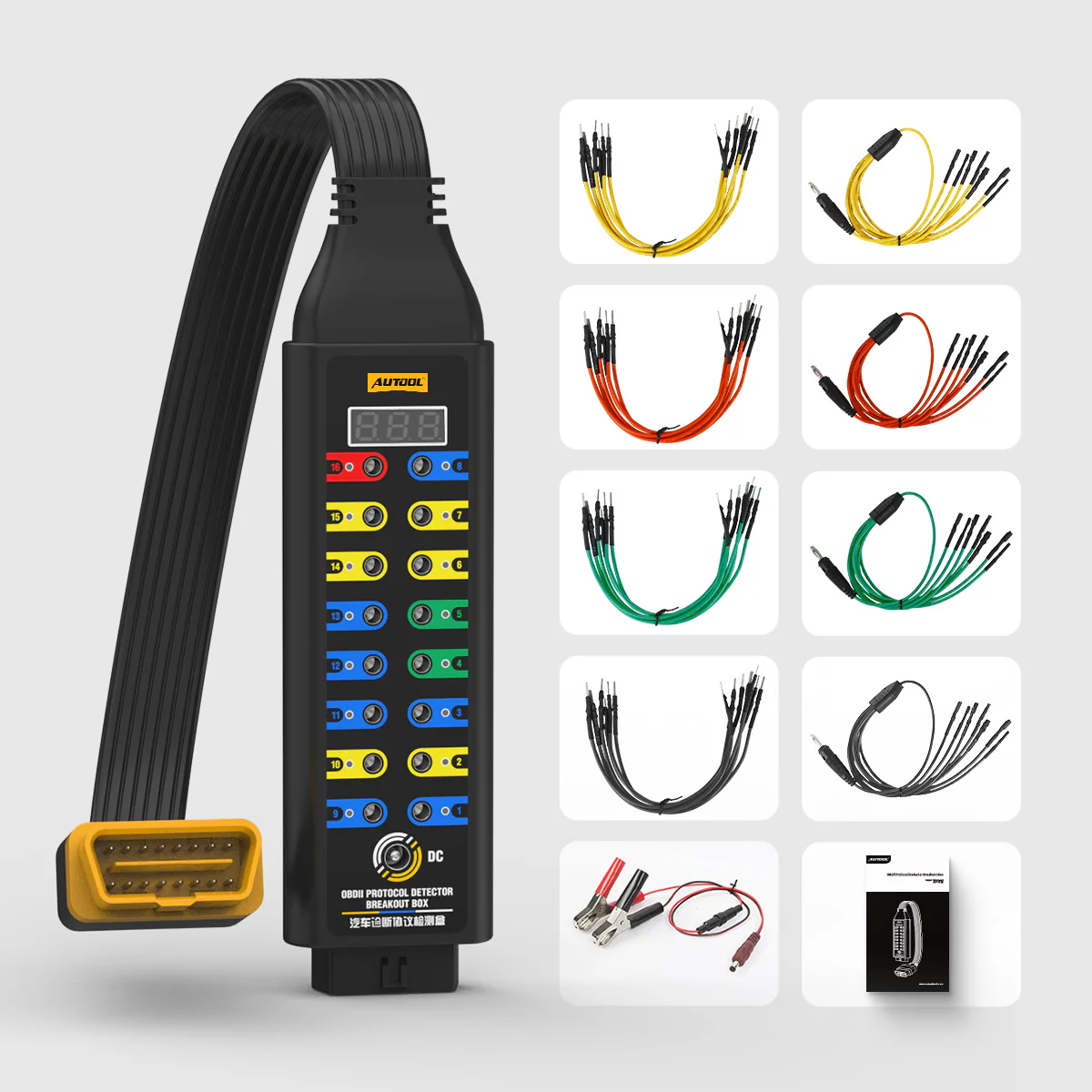
Комплектация
Check the Upgraded Breakout Box Package
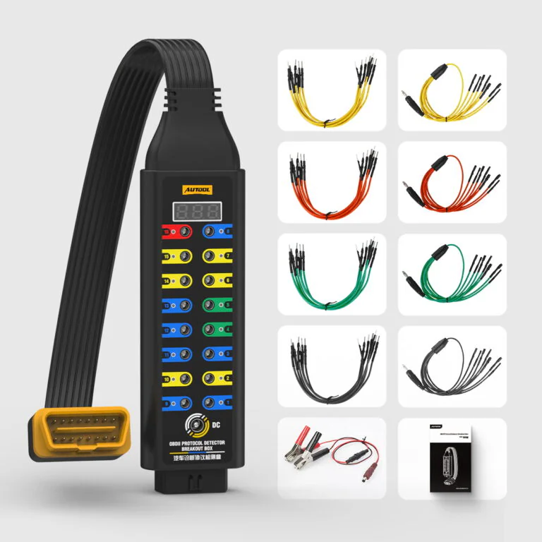
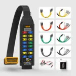
- Upgraded Breakout BoxMain device and 45 cm diagnostic connection.
- АксессуарыOnly the leads, power cable, and documentation shown for the selected version are included; confirm the option before ordering.
Часто задаваемые вопросы (FAQ)
Upgraded OBDII Breakout Box Fit and Function Questions
What Is An OBD2 Breakout Box Used For?
An OBD2 breakout box provides access to the OBD2 diagnostic link connector so users can monitor power, ground, protocol signals and voltage, while also making it easier to connect a diagnostic tool, multimeter or oscilloscope to the 16 OBD2 pins.
What Is The Difference Between Basic And Upgraded Version?
The Upgraded Version adds OBD voltage display, LED indicator and power cable support. The Basic Version is mainly for basic protocol, power, ground, 16-pin access and built-in input jack testing without these upgraded display and indicator functions.
Upgraded adds an OBD voltage display, LED indicators and 12 V temporary ECU backup support to the pin-access layout. Premium adds the 120 Ω mode; ask AUTOOL for the current specification and package list before purchase.
Does The Upgraded Version Support 120 Ω Series Resistor Mode?
No. The Upgraded Version does not support 120 Ω series resistor mode. The comparison chart identifies this function as a Premium Version feature.
Can I Use the Diagnostic Breakout Box with a Multimeter or Oscilloscope?
Yes. The built-in input jack fully emulates the 16-pin OBDII layout and can be used with a 4mm banana plug, multimeter or oscilloscope when you understand the vehicle circuit and pin function.
What Do The LED Indicators Mean?
The red indicator shows the pin 16 supply state. The green indicators show the pin 4 and pin 5 ground states. The yellow indicators show signal activity on the related communication pins.
Use the red, green and yellow LEDs as quick cues on the identified power, ground and communication pins, then use the circuit reference and an appropriate meter or oscilloscope for measurements.
Can It Supply Power To The ECU During Battery Replacement?
Yes. The DC power jack can connect to a 12V backup battery to provide temporary ECU power support during battery replacement or related service work.
What Should I Avoid When Using This Product?
- Do not directly short-circuit pin 16, pin 4 or pin 5.
- Do not use a jumper to short-circuit the input jack if you are not sure about the vehicle electrical circuit.
- Do not connect external load devices exceeding 1A, even though the product specification image lists a 2.0A load rating.
What Vehicles Is It Compatible With?
The OBD2 Breakout Box can be adapted to vehicles with an OBD2 interface and is designed for OBDII diagnostic link connector access.
Is The Breakout Box A Diagnostic Scanner?
No. It provides access and status indications. A compatible scanner, meter, oscilloscope, circuit information, and diagnostic method remain separate.
Нет отзывовПоделитесь своим опытом использования этого продукта первыми.