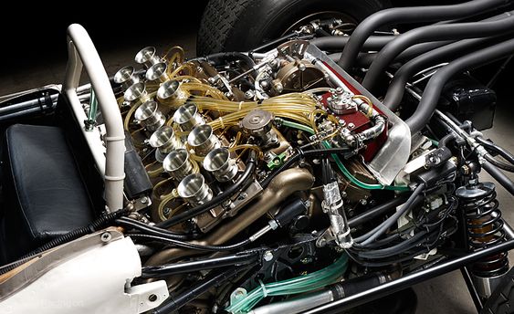
Patent examples from the original article
Several patent examples show different fuel-system design directions
New fuel system utility model patent
The new fuel system utility model patent relates to a new fuel system. It is characterized in that the fuel system includes a main tank body, a sub-tank body, and a refueling and exhaust pipe set between the main tank body and the sub-tank body.
A stainless steel pipe is also set between the main tank body and the sub-tank body. The two ends of the stainless steel pipe are connected to the main tank and sub-tank bodies through a joint assembly.
The technical solution is designed to be clever and compact. It makes maximum use of body space, meets customer requirements, and provides more selectivity for the development direction of future vehicles.
Energy-saving and environment-friendly fuel system patent
The energy-saving and environment-friendly fuel system utility model patent includes ECU, engine, battery, carbon pump, lock cover, and fuel tank assembly. The ECU is connected to the battery, engine, and carbon pump through lines.
The carbon pump is connected to the fuel tank assembly through a line, and the lock cover is connected to the fuel tank assembly through a line. The fuel system also includes a semiconductor cooling/heater, set between the battery and the carbon pump through a line.
This technical solution discharges clean gas into the atmosphere after hydrocarbons are adsorbed by the carbon tank, protecting the environment from hydrocarbon pollution. The negative bronchial pressure generated by the engine during driving desorbs hydrocarbons stored in the carbon tank to the engine for combustion, generating power, saving energy, and reducing costs.
Fuel system for internal combustion locomotive
The practical type of fuel system for an internal combustion locomotive includes a diesel engine, fuel tank, fuel pump, fuel filter, and pressure regulating device. The fuel tank is connected to the fuel inlet of the diesel engine through the main fuel inlet line.
The fuel tank is connected to the fuel inlet of the diesel engine through the main fuel return line and also includes a bypass valve and fuel preheater. The main fuel inlet line connects the fuel tank, fuel filter, fuel pump, bypass valve, pressure regulator, and diesel engine fuel inlet in turn.
The bypass valve outlet connects to the fuel preheater through the bypass oil line. The pressure regulator connects to the fuel preheater through the pressure regulator oil line, and the fuel preheater connects to the fuel tank through the auxiliary return line.
The patent sets up both the bypass oil circuit and the regulating oil circuit. System oil pressure realizes two steps of initial and fine adjustment through the bypass oil circuit and regulating oil circuit, making system oil pressure control more accurate and ensuring reliable diesel engine operation.